In this post I have explained about this special regenerative motor coil overunity phenomena which can be very interesting to the primary level experimenters like us.
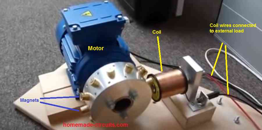
In this experiment a motor shaft is connected with a disc which has a few number of magnets attached radially at equal distance. An external high impedance coil is positioned in such a way that when the motor disc spin, the magnet move past the coil at a close proximity.
The result of the experiment is that, when the motor rotates and the external coil's wires are connected to a load, it does not load the motor, instead surprisingly it reduces the loading on the motor further. As the load on the external coil wires is increased it even further decreases the loading on the motor. Due to this, the motor RPM keeps increasing in a perpetual manner, as the external load increases. This opposite reaction is called the regenerative motor acceleration effect, which is a kind of perpetual overunity generation from the motor and can be used for many useful applications.
The whole explanation of the regenerative motor acceleration concept was researched and sent to me by one of the dedicated readers of this blog Mr. Thamal Indika
For more information on this subject you can directly email Mr. Thamal on this email ID:
intelligentdecent@gmail.com
Now I have explained more about this interesting regenerative motor overunity theory through the following description.
What is Regenerative Motor Acceleration
This is a good invention which was done by Mr. Thane Henis in UK and after years of experimentation, now the Uk scientists are going to fix this Special Generator to the Electric Vehicles, so that the Battery of electric Vehicle can be charged and also a real acceleration can be given to the vehicle, when the charging process is started. So there will be no need to stay hours of time in the charging centers to charge back the Electric Vehicle Batteries.
Before giving a better explanation to you about this special effec, I would like to answer your two questions.
How does the motor efficiency is increasing in the experiment because the external coil and the motor are not connected with each other?
Answer – Yes, The induction Motor and the External Coil are not connected each other. The Induction Motor is only used for the rotating of the magnet rotor in which all the Magnets are configured in the N S N S matter. The external coil is placed in front of this magnet rotor and when this coil is connected to a load the RPM of the Magnet Rotor is increased,. I really know why you are amazed, and usually the RPM of the Magnet Rotor should get slow down because of the Lenz Law as we all know. I have explained how this amazing thing is happening.
In the many relevant videos I saw that when the external coil was loaded the motor consumption decreased, so how is that happening?
Answer. Yes. The Consumption of the Motor decreases, when a l load is connected to the External Coil which has No Connection with the induction motor. Because when a Load is connected to the external coil, the RPM of the Rotor is increased by the coil, so that the motor plays a very little role in moving the Rotor. As there is a very less load for the motor, the consumption decreases. So Mr. Swagatam, Now I am going to give you a better explanation about this amazing phenomenon.
Why Conventional Fail to Produce Overunity
I would like to do a little explanation about this effect to you. When we use a Conventional Generator Coil consisting few turns of copper wire with a Magnet Rotor spinning in front of it, the Rotor speed will get decreased when the Generator Coil is connected to a Load. Thus, the motor fails to rotate perpetually and does not not produce overunity effect.
This is called the Lenz's law and this Lenz's Law consists of two brakes and that is why the Magnet Rotor speed gets decreased. I have explained how it happens.
When the N pole of the rotor magnet approaches the Core of the Generator Coil, the coil becomes magnetized as the coil is connected to the load and there is a loop circuit with a resistance caused by the load.
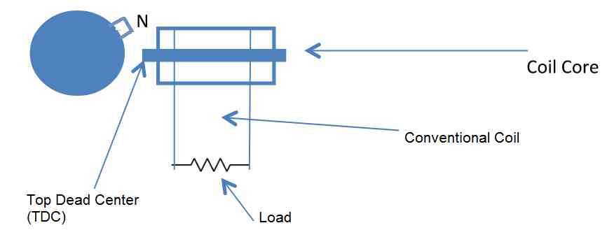
In this diagram, I have explained how the Lenz's Law causes 2 brakes and thus decreases the RPM of the Magnet Rotor, when the Conventional Generator coil is connected to the Load.
How Lenz's Law Inhibits Regenerative Action in Conventional Motors
When the N pole Magnet glued to the Rotor approaches the Coil Core, the Coil is very quickly magnetized, before the Rotor Magnet reaches the Top Dead Centre ( hereafter mentioned as TDC). So then the Coil Core will also become a N pole magnet and repels the rotor magnet which is also the N pole magnet and still approaching the coil core.
So this is the First brake created as per the Lenz's Law. It is caused by Magnet Repulsion.
Then when the Rotor Magnet passes the Coil Core, the Coil is demagnetized and then the coil core become a “ S” pole Magnet and it attracts the passing “N” pole magnet of the Magnet Rotor. So this causes the second braking as per the Lenz Law. So this is excatly how the Lenz's Law decreases the Rotor RPM and inhibits the regenerative effect in conventional motor coil systems, when the Generator coil is connected to the Load.
So now I am going to explain you, how the Lenz law becomes much delayed and how the Rotor RPM increases when we use the Special Regenerative Acceleration Coil ( hereafter mentioned as Regenx Coil ). In this Regenerative Acceleration Effect there are two Parameters.
The Coil should have many turns of copper wire and it should be high impedance, high resistance coil. The Rotor RPM should be high. The following is the Coil I made which has over 8000 turns of Guage 28 copper wire and it is about 600 Grams in weight. But when I was experimenting with my Small Set up, I understood that there should not be a very high speed in the Rotor and if we can make the coil a high resistance one then the rotor RPM does not play any significant role in making the effect.
My coil is a Bifilar coil and I connected the Bifilar coils in series and it has a high resistance. I used a small motor discarded from a DVD player and it is a 5V motor. When I supplied the power my magnet rotor gets about 1800 RPM and it is not too high, but I successfully achieved this effect.
So this is how the Regenerative Acceleration Effect happens.
As there are too many coil turns and the rotor is spinning in a very high speed, the Regenex Coil is not magnetized very quickly when the N pole rotor magnet approaches the Coil Core. But this Regenx coil gets magnetized when the N pole rotor magnet reaches the TDC as shown in the following diagram.
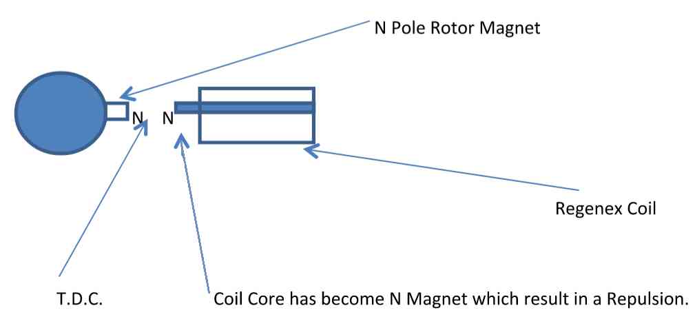
So as you can see in this configuration the Regenx coil is magnetized for “N “ pole, when the rotor magnet has reached the TDC, so that there is a repulsion in the Magnets and the rotor magnet is pushed away by the coil core (Because it is a N pole Magnet )and this is the first Acceleration effect of this regenerative acceleration effect.
As the rotor is in the N S N S magnet configuration, then this coil core simultaneously attracts the next S pole rotor magnet and it is the second acceleration effect.
Actually the Lenz law is happening here, But it gets much delayed because of the new alterations and accelerates the Magnet Rotor when connected to the load. we can charge some heavy duty batteries like 12V 7A or 12V Car batteries, if we can sue some big magnets with big copper coils like Guage 20 copper wire because they will provide much ampere.
In my small set up, I have used Guage 28 thin copper wire, but I can charge my mobile phone battery and also I can lit my lampshade and the RPM of the Magnet Rotor increases well when I connect these loads to the regenex coil and the current which motor takes from the drive battery gets much decreased when I connected the load.
I have also well understood that, if we can add more regenex coils with loads the rotor RPM increases simultaneously. For me this is a very amazing phenomena and as my first small set up worked very well, I am going to make a much bigger design.
My design will consist of two magnet rotors. One rotor will be the prime mover for the other Rotor which I will use for achieving this effect. So for the first rotor I will arrange magnets in the N N N N configuration and will fix around 6 to 7 bedini driver coils to get a high RPM with a 6V power supply from a Battery as shown in the following Video.
I hope to achieve this speed, using a 6V battery. But in my first experiment, I understood that we can achieve this regenerative acceleration effect using a normal RPM, if we can increase the number of turns of the regenex coil.
So then I will connect this driving rotor to the other Rotor (N S N S configuration) through a shaft and I will add a regenex coil set to charge another 6V battery first. Because when the Drive Battery gets discharged, I can swap the drive battery with the charging battery.
I will add another regenexx coil set to charge up a 12V 7A battery which I currently have and I can use it to supply the power for the small fan, the lampshade in my room and so on. In this set up, it will run indefinitely, because I always charge a 6V battery for driving rotor and swap it with the drive battery when it gets discharged.
Please note that I have experimentally proved that, if we add more regenex coils, the RPM of the Rotor increases simultaneously, and the prime mover takes much less current from the drive battery. It is marvelous fact and this will direct me to provide many overunity motors and we have reached this overunity situation 90 percent now.
I am sorry, my explanation is too long and it might have taken your worth time. But I did this, just to encourage you to make a device like this and see the results.
I hope you will reply me at your earliest convenience. Also please search in the “Youtube “ as “ Thane Henis Theory “ then you can find so many valuable lessons and videos about this special effect.
This is a small experimental set up created by Mr. Thamal, to demonstrate the effect of regenerative motor acceleration in response to the loading of the external generator coils.


Comments
Energy can be multiplied in resonant circuits if a resonant, in phase, input is greater than the circuit losses.
This is determined by the quality factor, Q, of this circuit.
Q = Xl/R = Xc/R where Xl and Xc are the reactance of the inductor and capacitor respectively and R is the Resistance, all in Ohms.
As an example in an inductor, the reactance will be:
Xl = 2π fL where f is the frequency in Hz and L is the inductance of the inductor in Henries. So, Q = 2πfL/R
In a series resonant circuit the voltage in the capacitor and inductor will be equal and opposite and Q times greater than the signal input voltage. The current will be the same as input signal current. So the power in each element will be Q times the input power.
In a parallel resonant circuit the currents in each element will be equal and opposite and will be Q times greater than the input current. The voltage across each element will be the same as the input voltage. So the power in each element will be Q times the input power.
allo I am fascinated with your knowledge and expertise! I see you have a number of different technologies to achieve overunity and I would like to know which one to use to power my home. If possible, I would like it to be between 3kw and 5kw.
So I am ready to accept your best suggestion how to accomplish this.
I receive a lot of emails and wondered if you use whatsapp. If so, it would be better for me so I won’t miss seeing whatever you send to me. I also use Telegram if that is better for you. Or if you have another solution you would prefer, just let me know.
I am very excited to be able to accomplish my goal of self power! and am excited for your response!
Thanks in advance for you generous help to so many people! Very kind!
greg loosli 801 427 4253
SourceOnesEmail@yahoo.com
Thank you so much for your interest in this subject, and for liking this website content.
However, since I do not have any expertise in the field of overunity generation, it would be difficult for me to suggest a practical working circuit to you.
Instead, I would suggest you to go for the renewable type of energy sources such as wind energy or sea wave energy which can offer you a free energy output, non-stop, 24×7.
Let me know if you want to know more about it…
1 You are to happy to help people make this.
2 A schematic with notes and a sketch of build will answer fine
details not understood by me.
3 I Thank you and am excited to learn this concept.
4 I am pleased to see such a helpful young man.
5 I can get this working with your help and I will help children.
Hello Gerard, thank you for your question.
Actually the above concept has not been tested by me and I am not well versed with the concept.
It was tested and investigated by my friend Mr. Thamal, so you can perhaps contact him through his given email ID, for the exact details of the design.
Or if you have any specific questions you ask me here, i will try my best to solve it for you…
In the many relevant videos I saw that when the external coil was loaded the motor consumption decreased, so how is that happening? – quotation- the Author’s answer is wrong at all. True is the – loaded coil is a kind of brake. All asynchronouse electrical motors are source of REACTIVE power (RP) =reactive electrical current and without a load the RP close to 99% of the motor’s NOMINAL power (written on it’s shield) = current is close to 190-200% of nominal current (printed on the motor’s shield) but with slidr in time=shift of phase, more load – less Amperes and phase shift of the RP. The RP close to 10-20% of Nominl power at mechanical load=brake load near 100% of nominal power. Also there is an Active power of the motor – which is given to load as a mechanical energy of rotation.
Both active and reactive currents are measured by a simple AmpereMeters (AM) and by all industrial PowerMerers (PM) as a total current = without separation of active and reactive currents!!!! Thats why all simple AM and PM is give decrease of current\power with rise of mechanical load – no depends – to load the motor by a pump or by a fun or by an another generator of by the magnets&coil or by not-greased bearings or by belt conveyor or by a gearbox or by else.
1-thinks to the Mr.Svagatam for the site and for His Honesty – He gave “keys” of another person’s frauds in the excelelnt description: “So then I will connect this driving rotor to the other Rotor (N S N S configuration) through a shaft and I will add a regenex coil set to charge another 6V battery first. Because when the Drive Battery gets discharged, I can swap the drive battery with the charging battery. and ….In this set up, it will run indefinitely, because I always charge a 6V battery for driving rotor and swap it with the drive battery when it gets discharged.”-quotation, thinks!!!!!! It is for a clever&atatntive only.
2-it would be interesting HOW = in all details – how to built the REGENEX coil in the described experiment. It could discover another large field of other person’s frauds and/or honest mistakes via espetials of physical design, yet.
Sinclary to the Mr.Swagatam.
Hi swagatam, I’m Joe, previously I have been following your projects and in the project concerning the over unity theory generator I had some doubts about if the generator uses one external coil or two
Hi Joe, I wish I could help you, however since I have not tested this theory practically it would be difficult for me to provide any useful suggestions to you.
The same as ALL of the other you-tubes of this kind; wires are “accidentally” reaching out of camera view. They go to the power source running the motor.
Terima kasih banyak