In the article below I have explained a compilation of simple yet accurate motorcycle voltage regulator circuits, which can be used for regulating the varying alternator voltage into a fixed DC voltage.
Voltage regulator circuit is very important in motorcycles and two wheelers since they ensure a regulated battery charging thus keeping the battery safe from over voltages. They also help to safeguard the electrical system and lighting system of the motorcycle, preventing them from burning or getting damaged prematurely.
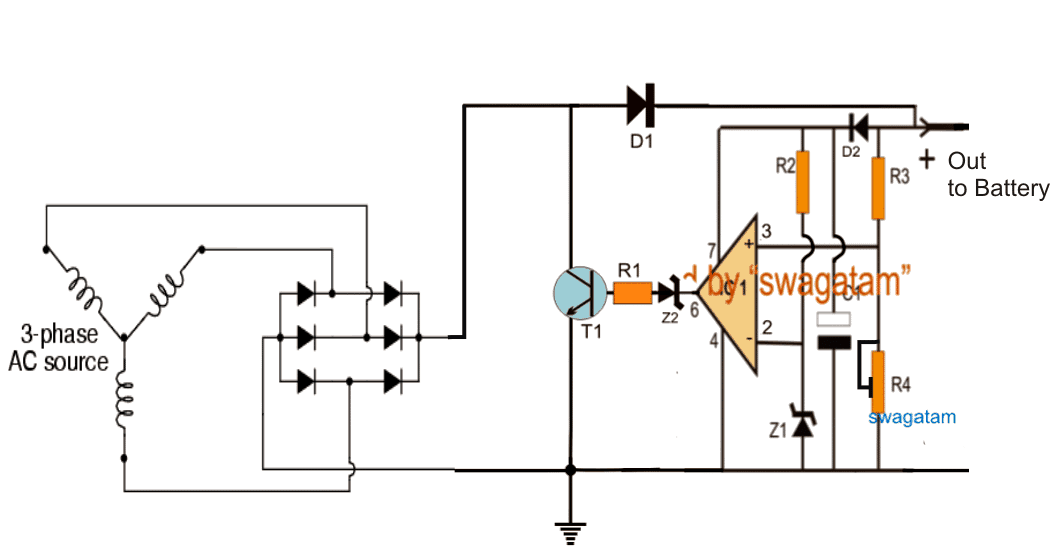
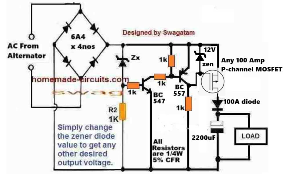
[New Update] High Efficiency, Lossless Motorcycle Regulator Circuit
The following motorcycle voltage regulator circuit ensures very low dissipation and a very high efficiency because it allows the output transistor to switch ON only during the periods when the AC cycle peaks are close to the intended output DC voltage.
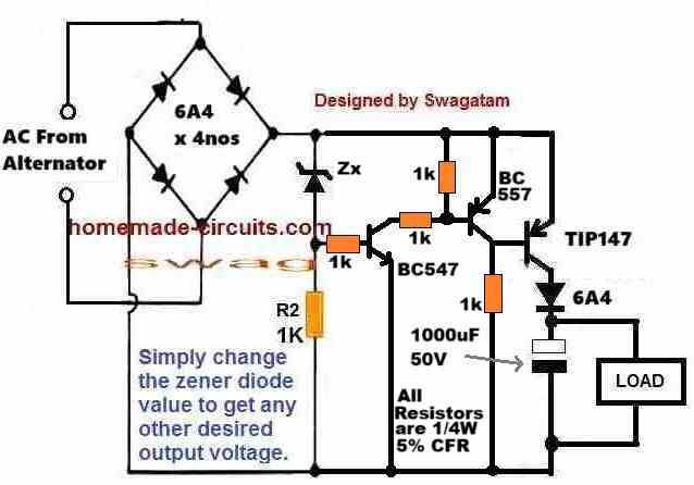
The inclusion of the two BJTs, BC547 and the BC557 convincingly keeps the TIP147 turned off as long as the AC waveform voltage level is above the zener diode breakdown level.
As long as the AC waveform voltage remains above the zener breakdown value, the zener remains conductive which in turn causes the BC547 and the BC557 to remain fully switched ON. In this condition, the BC557 keeps the base/emitter of the TIP147 short circuited, which in turn causes the TIP147 to remains turned off and non-conductive.
Now, whenever the AC waveform voltage dips below the zener breakdown value, the zener diode stops conducting, which means, the BC547 and the BC557 are also turned off. This removes the base/emitter short circuit from the TIP147 and allows it to switch ON fully. In this situation, the available instantaneous voltage at the emitter of the TIP147 quickly reaches the 1000uF capacitor, filling it up and simultaneously providing the operating DC for the attached load.
Next, as the waveform voltage continues its journey and climbs back above the zener breakdown threshold, its turns ON the zener, BC547 and the BC557, turning off the TIP147 yet again, and the cycle repeats.
So, as you can see, the TIP147 turns ON only during the periods when the peak AC voltage is close to the required output voltage, and as we know, for any linear regulator, the device remains cooler and dissipates minimum heat and is more efficient as long as its input supply voltage is close to its output supply voltage, which makes this regulator highly efficient.
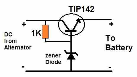
Simplest Motorcycle Voltage Regulator using a Single Transistor
The next circuit below explains how to build perhaps the simplest and cheapest voltage regulator using just a single zener diode and a power transistor.
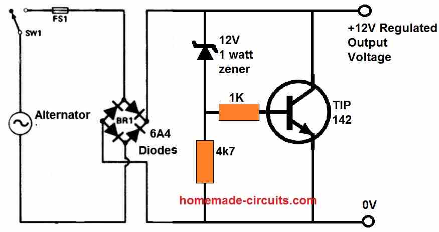
The circuit works in the following way.
As long as the rectified DC from the alternator remains below the zener diode breakdown voltage (12V), the transistor remains switched OFF due to the absence of a base voltage.
Now, as soon as the alternator DC tries to exceed the 12 V mark, the zener diode breaks down and starts conducting. This allows a base voltage to appear across the base/emitter of the transistor.
The transistor now switches ON and conducts.
When the transistor switches ON it short circuits or shunts the rectified DC, causing the alternator voltage to drop, until it drops below the 12V zener breakdown level.
When this happens the transistor switches OFF and the circuit returns to its previous state so that the voltage again starts rising, and yet again the transistor switches ON to regulate the alternator voltage.
The above ON/OFF cycle of the transistor keeps repeating a fast pace causing the output voltage to remain well regulated at 12 V.
The zener value decides the cut off threshold and thus determines the output regulated DC level.
Motorcycle Shunt Regulator Circuit using 2N3055 Transistor
The following design below explains how an op amp and 2N3055 transistors can be used to create a precision automobile voltage regulator circuit for enhanced battery charging.
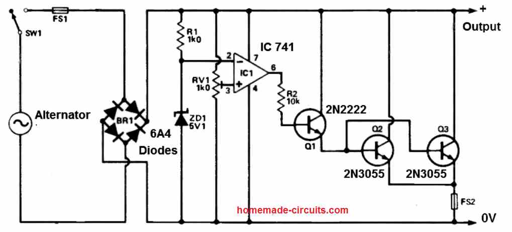
This circuit was developed to ensure control over the lighting system incorporated into an off-road motorcycle lacking lights.
The concept behind it is quite straightforward. Any surplus power generated by the motorcycle's generator is effectively shunted to ground, maintaining a constant and regulated output voltage.
The 741 chip serves as a comparator in this setup. Its output remains in a low state when the supply voltage falls below the desired threshold.
Conversely, when the supply voltage surpasses the target output level, the 741's output goes high, triggering the activation of transistors.
As a result, current is drawn from the alternator, leading to a reduction in the output voltage.
The regulator shunting activation threshold voltage is established by adjusting RV1. A bridge rectifier was opted for to ensure amplified power output during low engine speeds (idle).
To manage heat dissipation, the 2N3055 transistors are affixed to a sizeable heatsink, and the entire circuitry is coated with a protective layer of paint to prevent water infiltration.
Motorcycle Voltage Regulator using SCRs
The next design presented below is a Motorcycle Rectifier plus Regulator for a 3-Phase charging system of Motorcycles. The rectifier is full-wave and the regulator is shunt-type regulator.
By: Abu Hafss
A motorcycle's charging system is different from that on cars. The voltage alternator or generator on cars are electro-magnet type which are quite easy to regulate. Whereas, the generators on motorcycles are permanent magnet type.
The voltage output of an alternator is directly proportional to the RPM i.e. at high RPM the alternator will produce high voltages more than 50V hence, a regulator becomes essential to protect the entire electrical system and the battery too.
Some small bikes and 3-wheelers which do not run at high speeds, only have 6 diodes (D6-D11) to perform full-wave rectification.
They don't need regulation but those diodes are high ampere rated and dissipate a lot of heat during operation.
In bikes with proper regulated charging systems, normally shunt-type regulation is used. This is done by shorting out the alternator's windings for one cycle of the AC waveform. An SCR or sometimes a transistor is used as shunting device in each phase.
Circuit Diagram
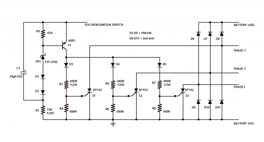
Circuit Operation
The network C1, R1, R2, ZD1, D1 and D2 forms the voltage detection circuit, and it is designed to trigger at about 14.4 volts. As soon as charging system passes this threshold voltage, T1 starts conducting.
This sends current to each gate of the three SCRs S1, S2 and S3, via current limiting resistors R3, R5 and R7. D3, D4 and D5 are important to isolate the gates from each other. R4, R6 and R8 help in draining any possible leakage from T1. S1, S2 & S3 should be heat-sinked and isolated from each other using mica insulator, if using common heat-sink.
For the rectifier, there are three options:
a) Six automotive diodes
b) One 3-phase rectifier
c) Two bridge rectifiers
All must be rated at least 15A and heat-sinked.
The automotive diodes are two types positive body or negative body hence, should be used accordingly. But they might be little difficult to contact to heat-sink.
Using Two Bridge Rectifiers
If using two bridge rectifiers, they may be used as shown.
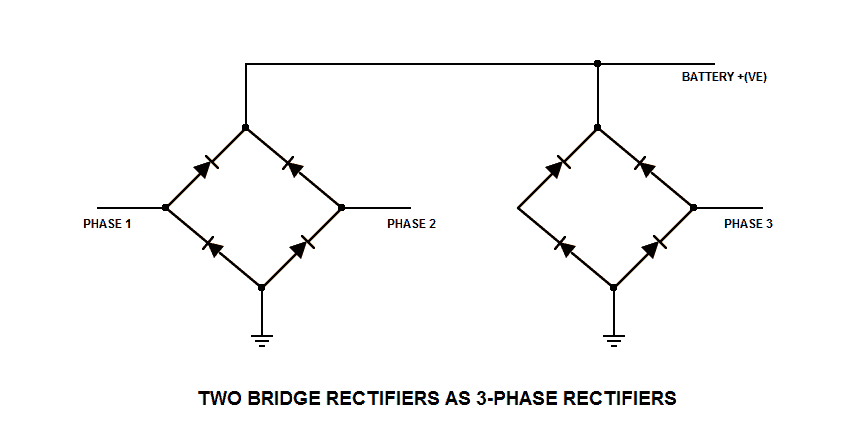
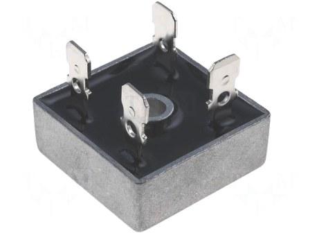
Bridge Rectifier
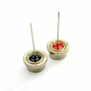
Automotive diodes
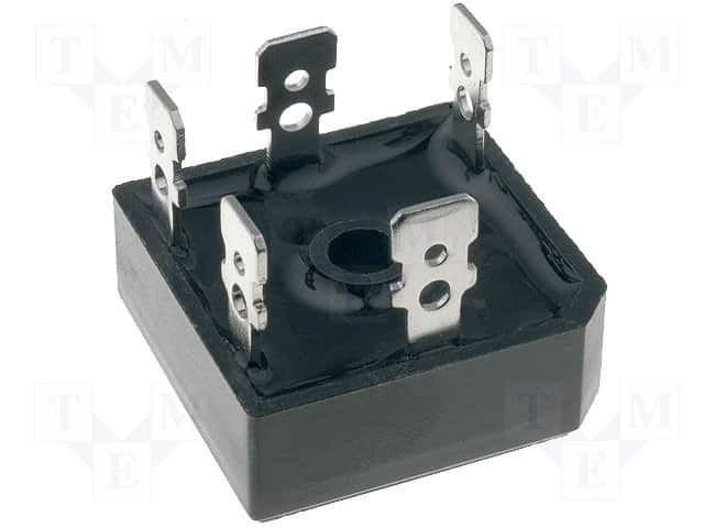
3-phase rectifier
Bridge Rectifier
MOSFET Full Wave Shunt Regulator Circuit
The next post below explains a full wave motorcycle shunt regulator circuit, requested by Mr.Michael. I have explained the circuit functioning in details.
How a Shunt Regulator Works
Shunt regulator is a device which is used for regulating voltage to some fixed levels by means of shunting. Normally the process of shunting is done by grounding the excess voltage, just as zener diodes do in electronic circuits.
However one bad aspect with such regulators is the generation of unnecessary heat. The reason for heat generation is the principle of its operation where the excess voltage is short circuited to ground.
The above practice may be implemented by simpler and cheaper means, but cannot be considered efficient and advanced. The system is based on destroying or killing energy instead of eliminating or inhibiting it.
The circuit of a motorcycle shunt regulator discussed in this article takes a completely different approach and restricts the in-flow of excess voltage instead of "killing" energy and thus stops the generation of unnecessary heat.
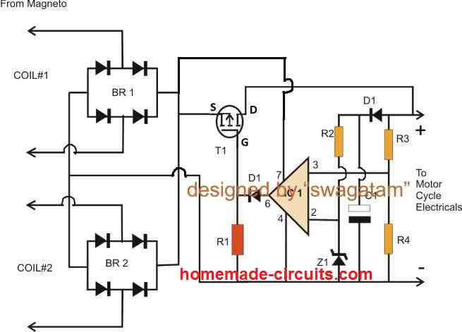
Circuit Operation
The circuit functioning may be understood as under:
When the mobike is started, voltage enters across the P-channel mosfet source/drain pins due to the gate trigger that becomes available via R1.
The moment the high voltage reaches R3, which happens to be the sensing input of the opamp, pin#3 of the IC senses an increased voltage.
As per the set reference at puin#2, the instantaneously reacts to the situation and the result puts the output of the IC to a high logic level.
The immediate high logic pulse restricts the negative base trigger of the mosfet, switching it OFF at that particular instant.
The moment T1 switches OFF, voltage at the junction of R3/R4 reverts to the original condition, that is the voltage here now drops below the reference level......this instantly activates the opamp output with a low logic signal which in turn switches ON T1 back into action.
The process repeats at a very rapid speed, keeping the output voltage marked with +/- at a constant level determined by the setting of R2/Z1 and R3/R4.
The above principle utilizes voltage inhibition technique of the excess voltage instead of shunting it to ground, thus saves precious power and also helps to control global warming in some way.
Parts List
- R1, BR2 = 10Amp bridge rectifier
- R1 = 1K
- D1 = 1N4007
- C1 = 100uF/25V
- IC1 = IC741
- T1 = mosfet J162
- R2/Z1, R3/R4 = as explained in this article
Shunting Excess Power to Ground is Recommended in Alternators
When it comes to alternators, the best way to restrict or limit excess voltage is to short the excess power or shunt the excess power to ground. This eliminates the rising current in the armature and protects the winding from heating up.
A voltage regulator using this method can be witnessed in the following examples:
Video Clip below shows an opamp based shunt regulator circuit, and its testing procedure
Parts List
R1, R2, R3 = 10K
R4 = 10K preset
Z1, Z2 = 3V zener 1/4 watt
C1 = 10uF/25V
T1 = TIP142 (on large heatsink)
IC1 = 741
D1 = 6A4 diode
D2 = 1N4148
Bridge rectifier = standard motorcycle bridge rectifier
How to Set up the Circuit
For a 12V system, apply a 18V from a DC power supply from the T1 side, and adjust R4 to precisely set 14.4V across the output terminals.
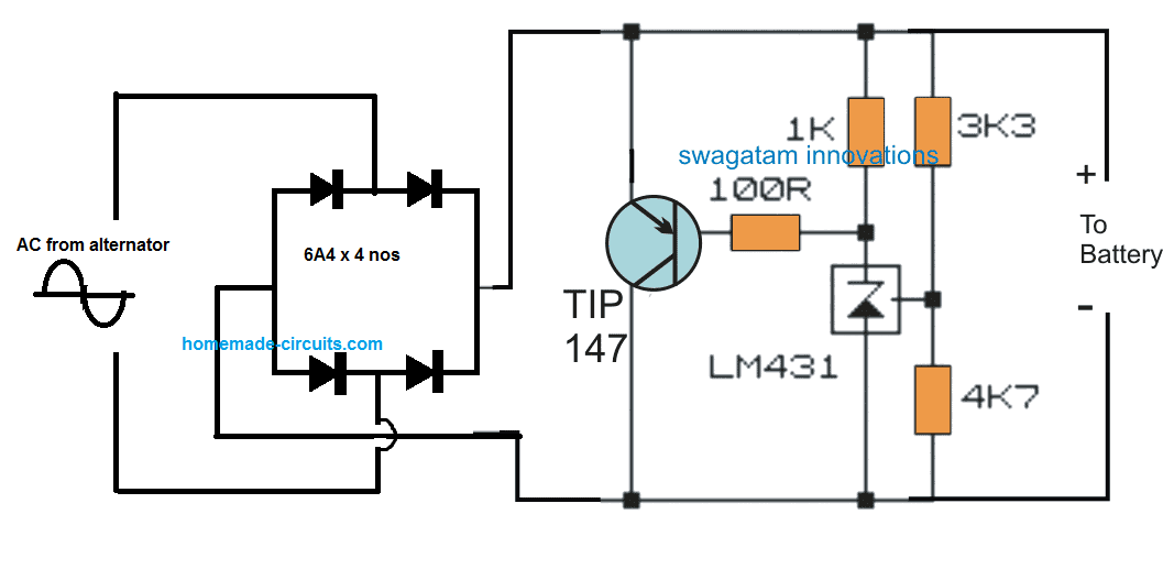
Simplest Regulator using TL431 IC
An even simpler motorcycle shunt regulator using the shunt regulator IC TL431 can be witnessed below, the 3k3 resistor can eb tweaked to chnage the output voltage to the most favorable level.
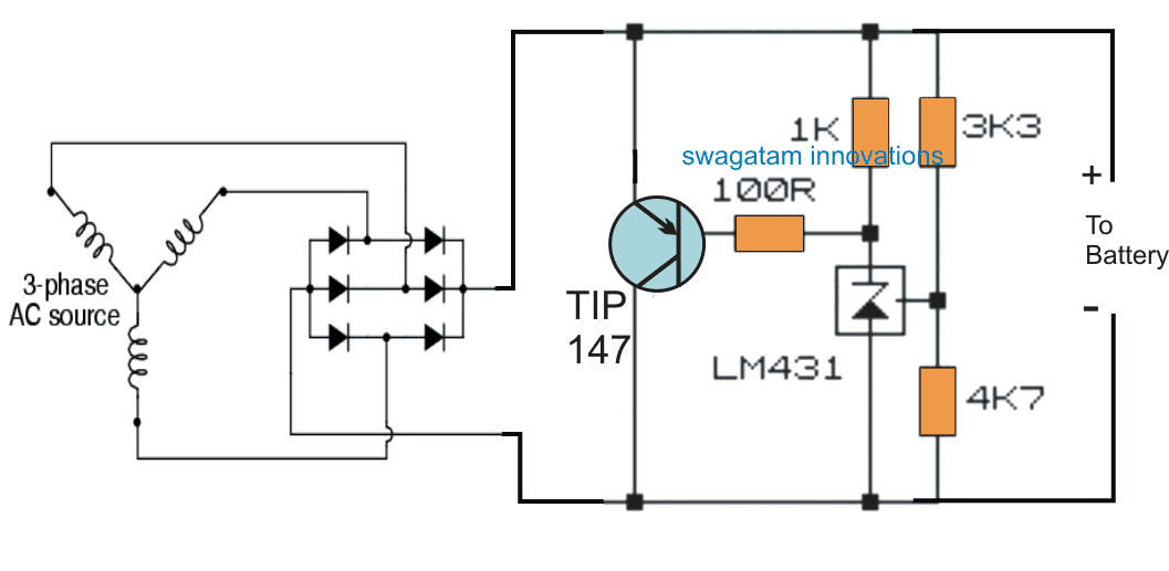
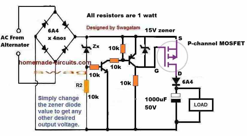
For single phase alternators, the 6 diode bridge rectifier could be replaced with a 4 diode bridge rectifier as shown in the following diagram:
3-Phase Motorcycle Voltage Regulator using IC 555
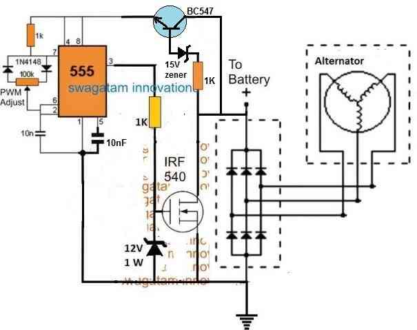
The next post below discusses a list of PWM controlled simple 3 phase motorcycle voltage regulator circuit which may be used for controlling the battery charging voltage in most two wheeler. The idea was requested by Mr. Junior.
Technical Specifications
hello my name is junior live in Brazil and work with manufacturing and recovery regulator rectifier motorcycle voltage and would appreciate a help u, I need a three-phase mosfet regulator circuit for motorcycles, entreda voltage 80-150 volts, correte Maximum 25A, maximum consumption of the system 300 watts,
I await return
att.
junior
The Design
The proposed 3 phase motorcycle voltage regulator circuit for motorcycle may be witnessed in the diagram below.
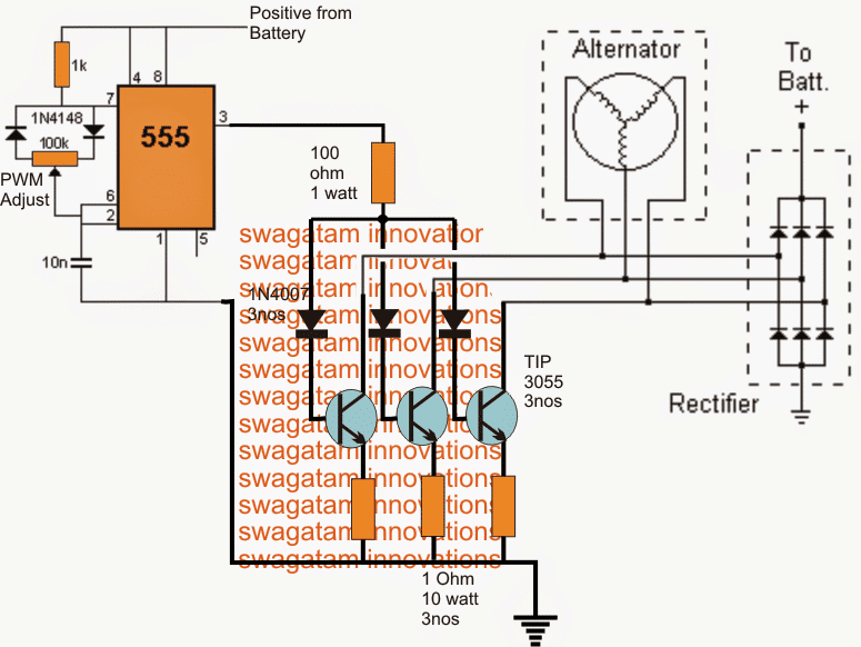
The schematic is rather easy to understand.
The 3 phase output from the alternator is sequentially applied across three power transistors which basically act like shunting devices for the alternator current.
As we all that while operating, an alternator winding could get subjected to huge reverse EMFs, to an extent which could get rip of the insulation cover of the winding destroying it permanently.
Regulating the alternator potential through the method of shunting or shorting to ground helps to keep the alternator potential under control without causing adverse effects in it.
The timing of the shunting period is crucial here and directly influences the magnitude of current that may finally reach the rectifier and the battery under charge.
A very simple way of controlling the shunting time period is by controlling the conduction of the three BJTs connected across the 3 winding of the alternator, as shown in the diagram.
Mosfets could also be used instead of the BJTs, but could be mush costlier than the BJTs.
The method is implemented by using a simple 555 IC PWM circuit.
The variable PWM output from pin3 of the IC is applied across the bases of the BJTs which in turn are forced to conduct in a controlled manner depending upon the PWM duty cycle.
The associated pot with the IC 555 circuit is appropriately adjust for obtaining the correct average RMS voltage for the battery in charge.
The method shown in the 3 phase motorcycle voltage regulator circuit using mosfets can be equally implemented for single alternators for getting identical results.
Peak voltage adjustment
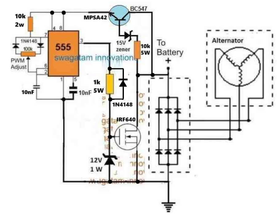
A peak voltage regulation feature may be included in the above circuit as per the following diagram, in order to maintain a safe charging voltage level for the connected battery.
As can be seen, the ground line of the IC 555 is switched by the NPN BC547 whose base is controlled by the peak voltage from the alternator.
When the peak voltage exceeds 15 V, the BC547 conducts and activates the IC 555 PWM circuitry.
The MOSFET now conducts and begin shunting the excess voltage from the alternator to ground, at a rate determined by the PWM duty cycle.
The process prevents the alternator voltage exceeding above this threshold, thus ensuring that the battery is never over charged.
Simplest Alternative without any PWM
Audio/Video Representation
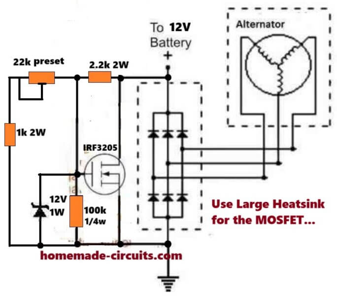
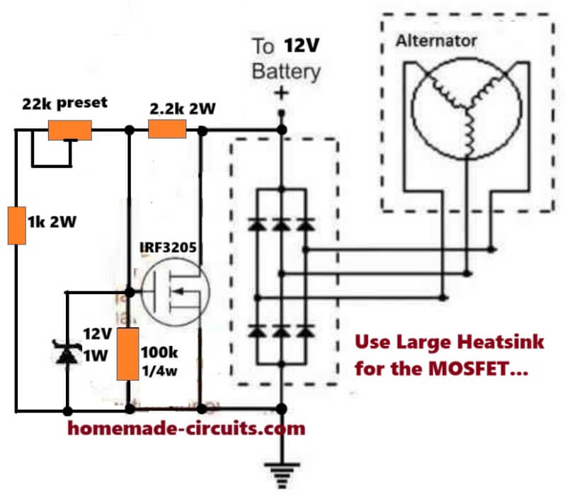
Here we see IRF3205 is used, resistance values also lower, so now the regulator part becomes stronger, less stress... What it does, simple.
- It rectifies the 3-phase alternator AC.
- It charges the 12V battery.
- It also stops the battery voltage from climbing too high.
When battery voltage rises and if it reaches the set point then the MOSFET turns ON, so now alternator output gets shorted to ground, extra energy gets absorbed there, battery stops rising further, that is how many motorcycle regulators work.
Those six diodes, they form a 3-phase bridge rectifier.
Alternator produces 3-phase AC but we need DC for the battery, therefore the diodes convert that AC into DC. That rectified DC then goes to the battery positive terminal and also to the circuit ground return.
Now we look at the sensing part. There is 22k preset, 1k resistor, and 2.2k resistor. These parts watch the battery voltage, they sample it.
The 22k preset sets the regulation level, so if you rotate that preset then the cutoff voltage moves. Normally we set battery limit around 14V to 14.5V. When battery voltage climbs above that point then the MOSFET starts conducting.
Now see the 12V zener diode. It protects the MOSFET gate. If this zener was not there then gate voltage could rise above 20V, and if that happens then the MOSFET gate may get destroyed.
So now the zener clamps the gate around 12V. There is also a 100k resistor. It connects between Gate and Ground.
Its job is simple. If there is no control voltage present then the MOSFET must stay OFF, so this resistor pulls the gate down to ground.
If this resistor was missing then the gate could float, and if that happens then MOSFET might turn ON randomly, which we do not want.
Now the main worker here is IRF3205 MOSFET. When gate voltage rises above roughly 4V to 5V then MOSFET starts turning ON. When gate voltage reaches about 10V to 12V then MOSFET becomes fully ON. If that happens then the rectified alternator output gets shorted to ground.
So now alternator current bypasses the battery and the battery voltage stops increasing.
Therefore the battery stays protected.
Now see the 2.2k 2W resistor. This one limits current flowing into the gate control network.
It also helps to stabilize the sensing part.
If this resistor was not there then the gate could receive too much current, then regulation may become unstable.
The 1k 2W resistor also limits current flowing through the preset and sensing path. So now the preset stays safe, it does not overheat, and adjustment range becomes stable.
IRF3205 is a good choice here. Its Rds(on) is around 0.008Ω.
Now let us see a small example.
If alternator current becomes 15A then power dissipation will be:
P = I² × R
P = 15² × 0.008
P ≈ 1.8W
So the MOSFET runs much cooler compared with BJTs. But still we must use a large heatsink, since sometimes current spikes happen and then heat will increase.
How To Adjust The Circuit
Adjustment is simple. Run the motorcycle engine.
Measure battery voltage. Then slowly adjust the 22k preset. Set the voltage around 14.2V to 14.4V. When battery reaches this level then the regulator will start shunting the alternator power.
What Happens At High RPM
When engine speed increases then alternator voltage also rises. If that happens then the MOSFET keeps switching fast. ON then OFF, then ON again, then OFF again. So now extra energy keeps getting shunted to ground and battery voltage stays stable.
But a few things must be remembered.
Use a very large heatsink.
Use rectifier diodes rated 30A or higher.
One more small improvement....
If we add a 15V TVS diode across the battery line then MOSFET gets extra protection, since alternator sometimes produces high voltage spikes, and then that TVS clamps those spikes.
Efficient Battery Charging through Motorcycle Shunt Regulation
The following email conversation between Mr Leoneard, an avid researchers/engineer and me, helps us to learn some very interesting facts regarding motorcycle shunt regulator drawbacks and limitations. It also helps us to know how to upgrade the concept simply into an effective yet cheap design.
Leonard:
You have an interesting circuit, but.....
My motorcycle has a 30 amp alternator, which I'm sure is RMS, and peaks at 43.2 Amps. Your 25 Amp circuit is not likely to hold up long at all.
However.....
In place of the rectifiers you suggest, an SQL50A is rated 50 Amps at 1,000 Volts. It is a 3-phase rectifier module, and should have no problem handling 45 amps peak. (I have two on hand.)
That also means the SCRs will have to handle that Amperage and three HS4040NAQ2 with RMS current of 40 Amps (non-repetitive surge to 520 Amps) should handle that quite well. Of course, they'll require a pretty healthy heatsink, and good air flow.
I'm thinking the control circuit should work pretty much as is.
I've replaced 3 regulators in the last three months and I'm about tried of throwing good money after bad.
The last one lasted a total of ten seconds before it went bad too. I'm about to build my own and if I have to build it to power a battleship, so be it.
Another thing I've noticed, the laminations used in the alternator are considerably thicker than those used in electric motors.
An 18-pole winding, and engine operating at highway speeds means much higher frequency, and far more eddy currents in the iron.
What would be the effect on those eddy currents if using a series regulator that would allow the voltage to go as high as 70 Volts (RMS)?
Would this increase the eddy currents to the point of overheating the iron, and risk damage to the windings of the alternator? If so, it would make sense not to allow the voltage to get above 14 Volts, but I still have 20 Amps coming from the alternator at 1500 RPM.
Me:
Thank you! Yes you must get rid of that high voltage which might put huge pressure on the alternator winding, the best way is to shunt it through heavy duty MOSFETs on heatsink
https://www.homemade-circuits.com/wp-content/uploads/2012/10/shunt-3.png
Leonard:
Actually, I'm not nearly as concerned about the effects of voltage on the windings. They appear to be coated with Poly-Armor Vinyl, which is also used in random wound stators operating at 480 Volts.
I'm far more concerned about the heat from the eddy currents in the laminations, since they are so thick. Here in the States, with 60 htz line current, the thickness of motor laminations are a fraction of what they are in the alternator.
At road speed, the frequency from the alternator can be 1.2 Khtz or higher. In other applications, that would call for a ferrite core to eliminate the eddy currents.
I'm trying to understand the role of eddy currents in this application. As RPM increases, so does the frequency, and the eddy currents as well.
A parasitic load to level off the voltage generated? A means of leveling off current generated at high RPM?
Just how much heat does that generate? Enough to burn out the winding at high RPM?
Located inside the engine, I can understand using engine oil to cool the assembly, however, with the centrifugal force of the flywheel, and the windings located inside that, I can't imagine any real amount of oil getting to them for cooling.
The highest voltage I've been able to read is 70 Volts RMS. That's not enough to arc through PAV coating on the wire, unless heat becomes excessive.
However, in shunting the excess to ground, Is there a counter EMF that opposes the magnetic field from the rotating magnets? And if so, how effective is it?
Me:
Yes, increase in frequency will give rise to more eddy current in an iron based core, and an increase in heat.I have read that shunt control method is good for motor based generators, but this will also mean increased load on the alternator wheel and more fuel consumption by the vehicle.Is fan cooling an option? the current to the fan can be accessed from the alternator itself.
Leonard:
I'm afraid that a cooling fan is not an option for the alternator. That is mounted internal, inside the engine, and on my Vulcan, there are two aluminum covers over that.(Replacing the alternator winding means removing the engine from the motorcycle.)
I do not see any way of reducing the eddy currents because they are induced by the magnets rotating inside the flywheel. However, I can reduce the current shunted to ground by raising the voltage of the shunt to 24 Volts, and following that with a series regulator set to 14 Volts.
In testing the alternator, I do not see much effect from counter EMF in reducing short-circuit current. I can load the alternator to 30 Amps, and by shorting the leads, I still read 29 Amps.
However, if using the eddy currents as a parasitic load to level off the voltage and current at high RPM, it seems to be quite effective.
Once the open circuit voltage reaches 70 Volts (RMS), it does not go higher even when engine RPM doubles. Shunting 20 Amps to ground (as done by factory regulators), increases the heat in the winding in addition to the eddy currents.
By reducing the current through the windings, the heat generated by the windings should also be reduced. That won't reduce the eddy currents, but should reduce the overall heat generated by the alternator, hopefully preserving the winding insulation.
Considering the coating on the windings, I'm not nearly as concerned about the voltage generated. Having worked in electric motor rebuilding for years, I'm aware that HEAT is the worst enemy of the insulation.
The quality of the insulation is reduced as operating temperature increases. At ambient temperature, PAV coating can hold 100 Volts "turn-to-turn". But raise that temperature by 100 C, and it may not.
I'm also curious.
Electric motors use a steel alloy with 3% silicon to reduce the resistance to magnetic field reversal within the iron. Do they include that in their laminations or omit the silicon to further reduce the increase of voltage and current at high RPM?
It does not add to the heat, but does reduce the efficiency of the iron, the higher the RPM. By increasing the resistance to magnetic field reversal in the core, the magnetic field may not penetrate as deeply into the core before it is required to reverse.
So, the higher the RPM, the less penetration by the magnetic field. The eddy currents may further reduce that penetration.
Me:
Your analysis makes sense and appears very much technically sound. Being basically an electronics guy, my electrical knowledge is not very good, so suggesting motor internal working and modifications can be difficult for me.
But, as you said in your last sentences by restricting the magnetic filed, the eddy current can be prevented from entering deep. I tried searching about this issue but couldn't find anything useful so far!
Leonard:
So, having worked with electric motors for 13 years, I have you at a slight disadvantage? Although, my studies have also been with electronics, and so was all my work until I found I could make more money working with motors.
That also meant I did not keep up with integrated circuits, and MOSFETs were delicate little things that could quickly be blown out with the slightest static charge.
So when it comes to electronics, you have me at a disadvantage. I was not able to keep up with new developments.
It's interesting that I have not been able to find much of my information in one place. Sort of as though none of the concepts are related to each other. Yet, when putting them all together, they begin to make sense.
The higher the frequency, the less turns are required to get the same inductive reactance. So the higher the RPM, the less effective the magnetic field becomes. It's about the only way they can keep the output constant once the output reaches 70 volts.
But in looking at the pattern on an oscilloscope, I'm not impressed. A millisecond of charge time, followed by 6 to 8 millisecond of grounded output.
Could this be why motorcycle batteries don't last long? Six months to a year, while automotive batteries go on for five years or more.
This is why I'm opting to "clip" the voltage level to ground at a higher voltage, and that clipping being constant.
Followed by a series regulator to maintain a constant charge rate according to what the battery, lights, and circuits require. Then by designing it to handle 50 Amps, I should never have to replace a regulator again.
I'm working with a 50 Amp rating, but I expect that by using a "clipper" the Amperage should be considerably lower than 20 Amps to ground.
Perhaps as low as four Amps. Then the series regulator allows the (approximately) seven Amps for the battery, lights, and circuits for the engine. All well within the wattage rating of the components and not enough voltage to challenge the coating of the windings.
You wrote a very good article about shunt regulators, but 25 Amps is just too small for my application. Still, it is good inspiration.
Me:
Yes that's right, duty cycle of 1/6 will not charge a battery properly. But this can be easily solved through a bridge rectifier and a large filter capacitor, which will ensure that the battery gets enough DC for effective charging.I am glad liked my article.
However the 25 Amp limit can be easily upgraded by increasing the MOSFET amp specs. Or may be by adding more devices in parallel.
Leonard:
At the same time, I'm trying to keep everything compact to fit into room available, so that large filter capacitor capacitor becomes a problem.
It is also not needed if all three phases are clipped after the bridge rectifier. All ripple is clipped off, and the series regulator maintains 100% charge time.
Your circuit also maintains 100% charge time, however the current you shunt to ground will be much higher because you are clipping it at battery voltage.
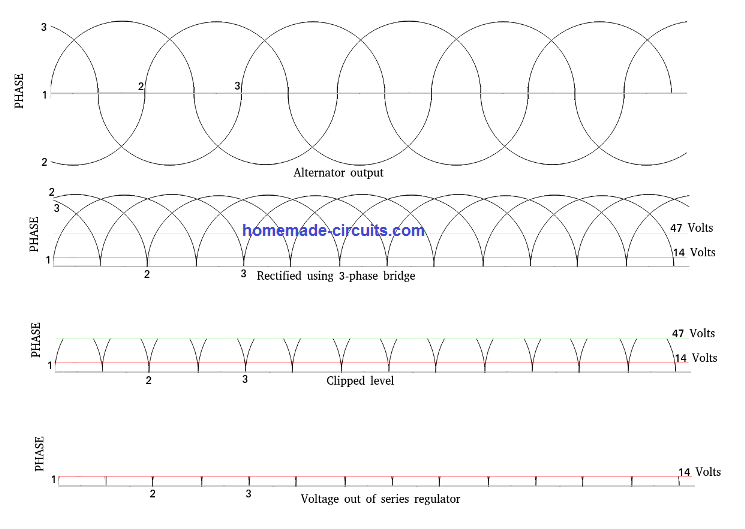
As you can see in the waveforms, there should be no capacitor needed. But by clipping at a higher level, the current shunted to ground should be lower. Then, dropping the voltage across a series regulator should not hurt anything.
There should be more than enough to keep the battery charged.
One note. Optimum charge voltage for a lead/acid battery is actually 13.7 volts. To hold it at 12 volts may not give the battery enough to start the engine. And my circuit is preliminary, and still subject to change.
The factory looks almost primitive, in the way it works. Their circuit charges the battery until it reaches the trigger level. then it shunts all current to ground until the battery drops below the trigger level.
The result is a waveform with a short, harsh burst of charge that could be as high as 15 Amps. (I did not measure it) That followed by a longer line with a slight downward slope, and another burst.
I've seen automotive batteries last 5 to 10 years, or longer. As a kid on a farm, my father converted one of the old tractors from six volts to a twelve volt system, using an alternator from a car. Fifteen years later, that same battery was still starting the tractor.
At the school I work with (Teaches motorcycle safety), all batteries need to be replaced within one year. WHY ? ? ?
The only thing I've been able to come up with is the charging system. Most of the batteries I've worked with are only rated for a 2 Amp charge rate, Up to 70 volts, capable of 30 Amps, applied to the battery terminals for short bursts may be causing internal damage and shortening the life of the battery.
Especially, in the batteries where you can not check the fluid levels. The only problem with the battery may be fluid level, but there is nothing you can do about it. If I'm able to check and maintain fluid levels, the battery life is extended considerably.
The leads coming from the alternator would be the metric equivalent of #16. According to the AWG table, that's good for 3.7 Amps as a transmission line, and 22 Amps in chassis wiring. On a 30 Amp alternator with a shunt regulator?
The shunt level and the Amperage should be an inverse proportion, so by clipping the voltage in half, I should reduce the Amperage significantly. In looking at the rectified waveform, the highest concentration of EMF is in the lower half. Logic would suggest the current will be reduced to a fraction. I'll find out when I put it into use.
On a 1500cc engine, I don't expect to notice the reduced drag on the engine, but my fuel economy may improve. And, I remember, back when they first started putting solid-state regulators on automotive alternators, the magic number was 13.7 Volts.
However, I was planning on setting my series regulator at about 14.2 Volts. Too high and the fluid evaporates more quickly.
You were far more helpful than you know. Originally, I had six different circuits that I was considering and was going to breadboard each of them.
Your article eliminated five of them, so I get to save considerable time and concentrate on just one. That saves me a good amount of work.
That makes it very well worth the time to contact you.
You have my permission to experiment with my schematic and see what you come up with. On various forums, I'm reading where a number of people are talking about going to series regulators.
Others caution against too high a voltage destroying the insulated coating on the wire. I suspect the happy medium may be a combination of both systems, but not shunting the full output to ground. The circuit is still simple, with few components, but not archaic.
Thank you very much for your time and attention. One of my sources for technical information is: OCW.MIT.EDU I've been doing engineering courses there for a few years now. You don't get any credit for doing them, but it's also completely free.
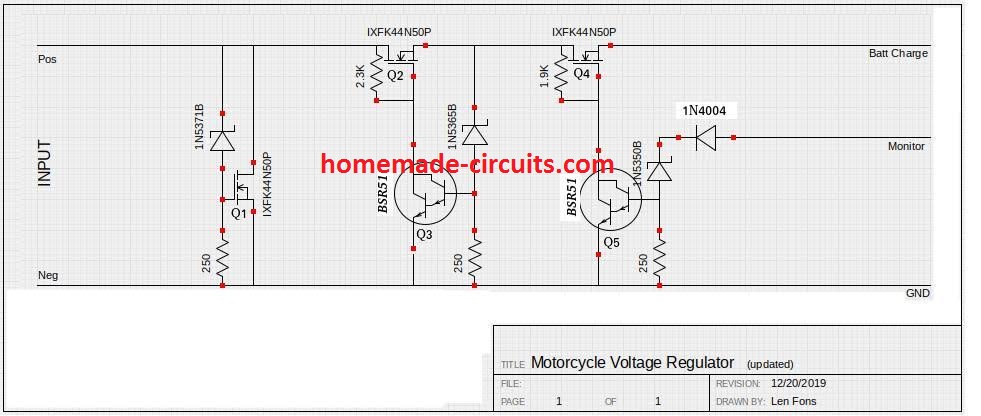
Feedback and Update from an Avid reader Mr. Leonard Fons
I've come up with a bit more that needs to be considered.
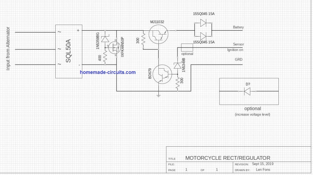
I'm using a MOSFET (IXFK44N50P) for the clipper and series regulators. Never did much with FETs because when they first came out, the least little static charge would blow them out in a heartbeat. So this is actually my first attempt to use them.
I assumed that, like junction transistors, the more power they handle, the more power needed to drive them. NOT TRUE. In looking again at the datasheet, I see that Gate current is plus or minus 10 nano Amps.
That is ten trillionth of an amp. They do not require a TIP142 to drive them. A one watt, high gain darlington will do the job very nicely. And the entire circuit will fit on one board. I still need another regulator housing for the rectifier. But I'm about ready to put this all together and try it out.
Of course, I will try it out before I actually mount it into the housing, but I don't expect to make any modifications.
Realizing that these FETs use almost no gate current at all makes quite a difference. I'll find out just haw accurate my theory is for the current to ground when clipped at 60 volts, rather than shunting all current to ground.
A when I pot it into the I have to insure that the FETs have no gap to the housing. That was another issue with one of the others. A sixteenth inch space between the components and the housing,
With that gap filled with epoxy, it's not very efficient at dissipating the heat for these motorcycle voltage regulators. By the time the housing starts getting warm, you'd burn your fingers on the components.
One change I may make is the series diode in the monitor line. A green LED located where I can see it while riding will let me know if it's charging.


Questions & Answers
Good day. Thank you for the many interesting circuits. I have consrtucted your very last motor cycle voltage regulator circuit using the mosffet IRF 540 with BC547 transistor and 555 timer.
Whilst the bike engine was idling, I have connected the circuit to thethre phase output, but not to the battery as yet, to firts measure the output voltage to be connected to the battery. The 1k 1 watt resistor and 15v 1 w zener exploded immediately. I disconnected and measured the output dc voltage from the rectifiers, it was 55V dc at 4000 rpm, and 145v at 8000 rpm. Between the electronic voltage controller supplied by you, there is no voltage limiter inbetween the rectifirs and the control circuitry to limit the output voltage from the rectifier to say 14.5 v maximum. Therefore my assumption is that is the very reason why the
electronic control circuit got destroyed. Please assist. Kind regards Hennie Nel.
Great page. I didn’t know motorcycle regulators worked this way, so thanks for that. I learned something.
One erratum I should note before I get into my rather lengthy comment: The circuit labeled “MOSFET Full Wave Shunt Regulator Circuit” is not actually a shunt circuit. It’s just a pair of bridge rectifiers feeding a linear regulator.
The shunt vs. linear regulator difference is pretty significant, but not quite what I thought it would be, which is interesting. Long story short, both designs are terrible gas guzzlers and I have some ideas.
I read a bit of the conversation you had with Leonard (not all of it, sorry) and I’d like to chip in, but I think maybe you and Leonard didn’t have the same understanding of some of the terms you were using. Just my impression, I might be wrong. Because of that, I might define some things that don’t need defining. No diss. My definitions might merely be mine, and I want to avoid misunderstandings.
While I’m writing this, I’m making common sense of what I’m saying by visualizing an experiment that I’ve done personally. It’s been making things understandable for me, so please let me share it with you. You can probably do this one in your head, but your bio makes me think you could duplicate this in reality in about three minutes with stuff from your shop.
Setup: One motor or alternator, doesn’t matter which, with a 3-phase stator. Bare wires, no regulator, rectifier, or other electronic gubbins on the stator. The rotor should spin freely by hand. A permanent-magnet rotor is easiest, but any kind of constant magnetization if fine. I used a brushless R/C plane motor.
Disconnect the stator wires, open circuit. Give the rotor a spin. It should spin fairly freely, even with a magnetized rotor.
Now, connect the stator wires together, short circuit. Try to spin the rotor. It will be practically seized. You can turn it, but it moves slowly and takes a lot of force.
The takeaway is that short circuits consume power.
[optional paragraph] We could talk about back EMF and eddy currents or whatever, but I don’t think we need to. We’re not going to find any surprises in the physics that make that first impression of how this works wrong.
[o.p.] This relationship holds up at every RPM. It takes basically zero horsepower to power an open circuit, and a short circuit will turn all the horsepower you can give it into heat.
The shunt regulators on this page work by shorting the stator coils. Making the rotor hard to spin for no work. Eating horsepower.
Because my motorcycle has a shunt regulator, my alternator is forced to use horsepower to produce a constantly high amount of electrical power. No matter how much I’m actually using, the maximum amount is always produced and rest is just wasted. Let me put some numbers on what’s happening: Assuming the 30-amp breaker on my regulator is an indication of the power of my charging system, that means that my alternator is constantly producing 30 amps at 14.6 volts, so 438 watts or 0.6 horsepower, most of it wasted as heat in the shunt regulator.
[o.p.] I have reason to believe that even more energy than that is actually produced but doesn’t make it to the regulator in a measurable way. It’s lost to the intentionally awful internal resistance of the alternator (more on that later) making the total wastage something closer to a whole-house space heater. Probably 2 horsepower constantly, which is like 4% of my full-throttle BHP, and quite a higher percentage the way I usually ride. I’m trying not to think about how much gas that’s been over the years.
[o.p.] As for the math in this discussion, the efficiency numbers get better if I use more power (grip heaters are free?) and everything varies with RPM. Being rigorous about the numbers is impossible. For the sake of conversation, let’s be very generous to the shunt regulator and say our nominal wastage is 30 amps at 14.6 volts. It’s way more than that, but whatever.
Leonard seems to be advocating for a linear regulator, which is honestly what I thought the current design would be. They work by disconnecting the stator coils when enough power has been pulled. Open circuit. Freewheeling whenever power isn’t needed. This will consume less current and therefore less horsepower. At high RPM, though, the stator voltage increases. Both you and Leonard were right about that. The consequences of that may be different than either of you realized, though.
[o.p.] About eddy currents and stator temperature… Total respect to you for this page and your work, but I gotta call it: If the magnets and coils and RPM stay the same, and current decreases, I can’t think of a single reason for eddy currents to increase. It seems like, all things being the same, the eddy currents would be higher in the core with higher electrical current. Moving magnets induce current, sure, but current and current alone is what induces heat and magnetism. Voltage is important because more voltage across a load will push though more current. Also, more voltage lets you wind more turns. Voltage by itself, though, does nothing. More capacitance, maybe. Longer arcs. The equation for magnetism is just current times the number of turns. For heat, it’s just current times resistance. So, unless you rewind the motor, the voltage just doesn’t matter, only current does.
So, yes, a linear regulator like Leonard describes will always produce less current and heat at the alternator compared to a shunt regulator. The benefit is significantly different at different electrical loads, though, and there’s an important tradeoff to consider.
[o.p.] As for the highest theoretical voltage the alternator can reach, it’s not that hard to hit in real life. You can reach that voltage by just unplugging the regulator and riding the bike around. I can’t imagine a part manufacturer being so corrupt as to make an alternator able to break down its own insulation. I would think insulation that thin and weak would harm the longevity of the alternator just due to heat and vibration.
[o.p.] The highest voltage an alternator can generate at a given RPM is its open-circuit voltage (nothing connected) as defined by its Kv constant. Kv is German for voltage constant, specified as volts per 1000 RPM. For any given motor, Kv will be constant as long as the windings and magnets stay the same. You can know what voltage to expect by doing math with the Kv, but on a motorcycle it’s probably easier to just measure it: unplug your alternator, connect an oscilloscope, start the engine, record the RPM and peak-to-peak voltage, and then do simple math to calculate what the peak voltage would be at redline.
But measurement is hard, so let’s use Leonard’s 70v guess instead.
Actually, everything from here forward is napkin math based on other people’s best-guess numbers. The effects described are real, and I think the numbers correctly portray how various things work, but these aren’t measurements. In particular I’m completely fudging Ohm’s law when it comes to the alternator, but that thing is garbage and I don’t respect it. I could take my oscilloscope down to the garage and turn these guesses into measurements, but now that I know my bike doesn’t have high-voltage AC to play with, I’m not interested.
At zero electrical load Leonard’s ideal linear regulator will consume no power, which is 100% efficient and impossible to beat. Literally infinitely better than a shunt or anything else that exists, but especially shunts, which are always pulling full power at 0% efficiency.
At the full 30 amps, shunt and linear regulators perform exactly the same. Our alternator has sucky internal resistance for some reason, (probably so the shunt works better, but whatever,) so the voltage at the alternator drops to 14.6, pulling the whole system down 21% efficiency. At the regulator, there’s no voltage left to drop and no current to sink, so the regular itself is the most efficient part whether it’s linear or shunt.
At 15 amps, the shunt regulator will pull 30 amps from the alternator at about 21% efficiency. That wasted energy mostly heats the alternator. The regulator is 50% efficient at that current, making the whole system about 10% efficient. The regulator produces 219 watts of heat at 15 amps, which is probably too hot for something you want to own a long time.
At 15 amps, the linear regulator is literally killing itself to use less power. We’re pulling 15 amps from the alternator, so it’s doing ok. Half its max current, at the full 70 volts, which makes it basically perfectly efficient. However, the regulator is a variable resistor wasting that efficiency by metaphorically riding the brakes to keep the downstream voltage at 14.6, making the regulator and the entire system 21% efficient, which would be terrible if it weren’t twice as efficient as the alternative. The regulator itself wastes the other 79% of the entire system power to generate 831 watts of heat, four times the shunt regulator, concentrated in a sensitive electronic part that may or may not have airflow over it and might burn out or melt things. Really.
Now, those are both terrible, so let me introduce you to the DC-to-DC converter. The most expensive option, but it pays for itself in efficiency. We take a 3-phase bridge rectifier (cheap, one-chip options are available, why don’t all the designs use them) and feed it into a DC-to-DC converter. It sips amps at whatever voltage the alternator wants and converts high-voltage watts into high-current watts (or vice-versa) at 90% efficiency. At 15 amps load, it only pulls 3.5A from the alternator while producing just 22 watts of waste heat.
Biggest problem with DC-to-DC converters? Size, and nobody else is putting them on motorcycles. There are tons of them available, but they’re literally designed for and marketed to engineers, they probably won’t fit on your bike, and weatherproofing is your job.
The most efficiency for the dollar would probably be alternators with variable energizers like cars already have. No regulator, just create the exact right amount of rotor magnetism to make only the energy you need. You would need to replace some or all of the permanent magnets with coils, which adds complexity and requires a bit of wasted power, but it’s probably worth it.
Hi, sorry, that’s happening due to high alternator voltage and wrong part values….please upgrade your circuit as shown below:

Please replace the BC5547 with MPSA42 BJT.
Actually the PWM control is simply not required…you can just try the following version for a better regulation with minimum part count:
Great , thanks for your quick reply and assistance.
Regards.
My pleasure!! Let me know if you have any further issues with the circuit…
Hi Swagatam,
I have read this page several times now, mainly because I am not an electrical or electronic engineer but a mechanical one. Many years ago (~1989), the regulator/rectifier on my CBX Honda failed, and at the time, I barely had enough money to put fuel in the beast, let alone shell out for a new device. I built a simple shunt regulator very similar to the second example in your page, the one with a single transistor, by bumming components out of the trash at my place of work. It worked great, and was still going strong when I sold the bike some 7 years later.
I too have noticed Leonard’s comments about the longevity of the average motorcycle battery; I never had to replace one on the CBX. Today, I have a Honda CB1000 (Big One) that uses a 3 phase alternator, and although the machine is functioning perfectly well, it dates from 1995, so parts are becoming rarer. I know I could just fit a modern day MOSFET based replacement should the RR go west, but this will not solve the battery longevity problem to which Leonard alludes. I bought a new battery for the CB ~3 years ago, and it is already showing signs of weakness. Benefits in reduced fuel consumption are also not to be ignored, and a straight forward shunt regulator does not help with this, if I understood the discussion with Leonard correctly.
I was wondering if you have received any feedback from Leonard on his series regulator idea at the bottom of the post? Did he build one and was the higher voltage level in the alternator as expected, yet manageable?
As a mech. eng., electrical/electronics are not intuitive for me, but as I have time now, I’d like to understand the concepts.
Kind regards
Thank you George,
However, I don’t think the regulator quality affects the battery life, rather a regulator may affect the alternator longevity.
For example, if the voltage regulator is adjusted to limit the max charging voltage to 14V for a 12V battery, then the battery will be perfectly alright and can have a long working life. However, if the regulator is causing the alternator to heat up then definitely the alternator life will be reduced and winding may eventually heat up and get shorted.
In that case I would recommend you using a PWM based regulator, such as the following one which not only keeps the battery charged optimally, it also makes sure the alternator runs coolly and without any unnecessary stress…
Thank you for taking the time to reply to my questions Swagatam, it helps me understand the concepts. In my opening remarks, I was not questioning the quality of the regulator, but more the fact that Leonard seemed to be saying that shunting the alternator output at ~12V means the battery is only being charged ~1/6 of the duty cycle. If I understood correctly, Leonard was saying that shunting the voltage at ~24V should mean a charge over considerably more of the duty cycle, while at the same time reducing the current in the alternator windings which will reduce the heat generated due to the shunt to ground at the higher voltage. A large capacitor will help with the first issue (smoothing the charge over the duty cycle) but will do nothing for the second issue (current in the alternator windings due to the shunt). If an alternator’s insulation is designed with 12V in mind, then allowing 24V should be OK or it is going to be flaky even at 12V, but I guess you wouldn’t want to push this any higher.
On the other hand, I am inferring from the PWM circuit you indicated that it not only ensures charging over a good part of the duty cycle, but also prevents excessive load on the alternator windings due to the shunt, in which case why did you not suggest this to Leonard? Maybe you only thought of it after your exchanges with him.
I suppose like many situations, there is more than one solution to a problem, and what I am trying to discern is which of these circuits will give me the best chance of making a robust and lasting solution to the issues of poor battery life and avoiding excessive heat in the alternator.
Thanks
Thank you George, you have understood Leonard reasoning quite well. But the idea that shunting around 12–14 V means battery charges only for small part of waveform, that does not sound correct.
In permanent-magnet motorcycle alternator, power is produced continuously with RPM, so it is always there. Shunt regulator just diverts extra energy once battery reaches regulation voltage. Charging therefore is continuous, not only at brief peaks.
Shunting at higher voltage like 24 V may sound like it will reduce alternator current and heating, but in PM alternators, stator current is mainly set by magnetic field strength and speed, not by DC clamp voltage. So copper losses and core losses in stator do not reduce much just by raising shunt voltage.
You are correct that a large capacitor helps smooth DC and improve charging behavior, but it does not reduce stator heating or regulator heating.
PWM series-type regulator can reduce alternator loading, so yes that is why such regulators exist commercially. But they are more complex to implement reliably and they were outside scope of Leonard original shunt-based discussion. For most DIY applications, a properly rated shunt regulator with good heat sinking becomes the most practical and robust solution.
hello Swagatam, it’s Giuseppe from Venezuela, I experienced several of your circuits here, they seemed very good to me, but like every experimenter, I installed a switching source to the stator of the three-phase motorcycle. It is between 80 and 100 volts on foot, which allows me to charge the battery. and maintains 13.8 volts at high speeds. The question is what damage can I cause to the stator with a consumption of 5 and 7 amps. There is no obligatory ground bypass but it does take the ground from the source to the chassis of the motorcycle. I would like your opinion, thank you from Venezuela
Hi Giuseppe, thanks for the kind words and greetings from India….
In general pulling around 5 to 7 amps from a three-phase motorcycle stator usually does not harm anything, as long as the stator is not being driven too hard or getting hot over time. These stators are anyway made to handle decent current because normally they feed a rectifier-regulator and from there the battery and all the bike electrical loads together, so current handling is part of the design.
The thing to really watch is not the voltage value itself but the total power being drawn. If your switching power supply is loading the stator beyond what it is rated for then slowly the stator windings can start heating up….and get damaged.
But because you are seeing a steady 13.8 V at high speeds is actually a good sign, it shows the system is still regulating properly and not collapsing. But at lower RPMs, if the stator is still being forced to deliver high current continuously, then heating can increase because cooling is also reduced at low speed.
About grounding, using the motorcycle chassis as ground is normal practice and usually fine. As long as the ground connections are solid and low resistance, it should not create any special problem.
Good day Sir Swagatam, I just done making your first Circuit but I used IXTH90P10P. P channel mosfet instead of BJT transistor. I test it using 24v transformer. And it has an output voltage of 14.6v but if I put load to it of about 4amps, the output voltage has drop to 11v and the transformer is like humming or clicking sound. Is that normal Sir? I just want to know it because I’m afraid to put it on my motorcycle
Thank you Raymund, for your kind feedback.
If you use a MOSFET in place of TIP147 BJT, make sure to add a 15V or 12V zener diode between the positive line and MOSFET gate, otherwise your mosfet could burn immediately.
Yes, the voltage will drop with this circuit…. to compensate this please increase the output capacitor value to 2200uF or higher.
Thank you so much for your reply sir Swagatam, I aready connected it on my motorcycle stator. After testing the output is 14.6v but after i rev the throtle to the max rpm the resistor is smoking. (1.the resistor from gate to ground) (2.the resistor from base of MPSA92 to colector of MPSA42) and (3.the resistor from Negative side of 15v zener diode to base of MPSA42.
No problem Raymund, thanks for the update…. please increase all the 1k resistors to 10k 1 watt or 2 watt, then it will become perfectly alright…
I’m sory sir swagatam but is it ok to put 10k resistor on the base of mpsa92 and mpsa42 because according to datasheet they have very low current gain(hfe).
Raymund, you are right, but as you can see we are using MOSFET at the end, which can be switched ON/OF with very small current, that is why it is fine to use 10k for your MOSFET based circuit…
Ok sir Swagatam, thanks for helping me to fix the problem of my regulator circuit. All I can say is thank you. thank you so much, I really appreciate your kindnes. I’m from Philippines. I’m one of your fan for making different electronic circuit and helping other electronic hobbyst. I already build some of your square wave inverter and many more.
You are most welcome Raymund, and thank you for your kind words, I am glad I could help…please let me know if you have any further issues with your circuit…
good day sir Swagatam, it’s me again Raymund, what if the mosfet will get broken and the output voltage becomes unregulated, and if that happens my motorcycle ecu (electronic control unit) will be damaged too. For that, I want to connect over voltage disconnect or cut off if 15v is present. Do you have some circuit diagram with it.?
Good day Raymund, yes that’s easily possible.
You can just put the following circuit between your MOSFET output and the load:
use a 15V zener for the zener diode, and increase the zener value of your MOSFET circuit to maybe 18V.
I’m sorry sir Swagatam but what modification is needed to use mosfet instead of bjt for more current.
…in my previous comment, for that MOSFET version, please make sure to add another 12v zener parallel to R3…
Raymund, if you want to use MOSFET, then please use the following version:
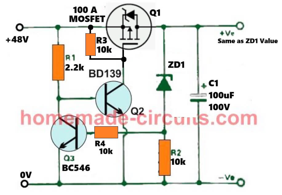
At the shown 48V side, use the 15V output from your previous regulator circuit.
Use 15V zener for ZD1 in this circuit also.
The MOSFET can be IRF9540
can I use IXTH90P10P too? thesame mosfet which i used on my circuit?
Yes, definitely, you can use the same one on the new circuit also…
Thank you so much Sir Swagatam, I will try it and give you some feedback. need to buy the parts first online.
gracias Swagatam por todos los consejos te deseo lo mejor y estaré pendiente de las observaciones que has hechos abrazos desde Venezuela
Thank you so much Giuseppe for your kind words. I truly appreciate your support. I’m glad the advice helped and I’ll continue sharing my observations. Warm greetings to you in Venezuela.
hello Swagatam, it’s Giuseppe. With another question, I can test these circuits with a three-phase transformer that has 60 volt alternating current outputs. The circuit I made was the one with the three 2n3055 transistors and the pwm with the 555. Thank you very much from Venezuela
Hi Giuseppe, Yes, you can test all these circuits, with a 60V AC 3 phase supply….along with the 2N3055/555 circuit
hello Swagatam, I have a Burman 650 and I am going to make the circuit where the three 2n3055s are. Tell me, it would be the right one for that type of three-phase current and voltage. Thank you. I am in Venezuela
Hello Giuseppe,
Yes, the 2N2222 and the 2N3055 based regulator circuit is very accurate and can be used with any vehicle, as an alternator voltage regulator. Just make sure to use a 3 phase bridge rectifier for the 3 phase AC supply….
muchas gracias por tu ayuda un gran abrazo desde venezuela
Thank you Giuseppe for your kind words, much appreciated…
hello sir, in my old honda unicorn bike i installed lithium phosphate battery(12v6ah) with bms (4s30a) for self start which need charging voltage 14.6v . it is working fine till now. I want to know is it safe to connect bike battery charging voltage to bms directly? is there any dc filter or regulator required in between? pls guide.
Hello vijay,
If your battery charging voltage is DC and within the maximum tolerable range of the BMS, then you can use it without any worries..If not then you will need a bridge rectifier and an appropriate regulator stage in the middle…
thanks
If my snowmobile has no battery, a 160W stator and all loads are powered by AC, Which design do you recommend? I would leave the DC side disconnected. The original voltage regulator only have two wires. Thanks!
Hi, I would rather recommend you the following diagram;

Thank you ! I will try the circuit and give you some feedback.
Sure, no problem…
I would really like to be able to build A three-phase regulator. I have limited knowledge, However I’m able to learn and understand very quickly. I do have experience and I have tools. Also,I use reference efficiently and am Beyond diligent. Thank You and your efforts and accomplishments are admirable.
Hi, as i can see, 3 phase regulators are already explained in the above article…do you have any specific requirements in the design…
As for the 1st schematic, Would it be possible to mount 4 TIP147 ( matched) in parallel to have 60A circuit ?
Tnx
Yes, that may be possible, but I think it is better to use an MOSFET instead.
Tnx for the reply, so it’s possible to fit this on a big old motorbike with a 50-60A 3 phase sytem using a Mosfet ?
Reducing heat in the engine by not shorting out the coils would be wonderfull !!!
What changes are needed on the circuit and what mosfet (or maybe IGBT ?) ?
As per my mind simulation, the first circuit will do the job perfectly regardless of the load current, if a correctly rated MOSFET is used for the output transistor. You can try the following configuration:
Hello, I would like you to publish a diagram of a charging system, that is, an alternator voltage regulator for a car, with the component values so I can put it together. I’ve only seen you publish almost all motorcycles. Could you help me and give me a hand to make one because mine broke? Thank you very much in advance.
Hi, thanks.
If you want a battery charger regulator for your car, then you can consider the following designs:
https://www.homemade-circuits.com/car-alternator-regulator-circuit/
If you want a regulator for your electronic systems of the car, then you can add the following circuit after the battery:
https://www.homemade-circuits.com/15v-10-amp-adjustable-voltage-regulator/