In this post I have explained a simple morse code lamp flasher circuit which may be used for model lighthouse signalling applications. The idea was requested by Mr. Frank Gardner.
Technical Specifications
I am in need of a unique flashing circuit.
I have built several exact scale models of the light house at Yerba Buena Is. in San Francisco Bay. The models are for presentation to members of the Coast Guard Auxiliary.
The recipients know the aids to navigation. Therefore, I'd like the light to flash in the authentic sequence. The correct sequence for this light house is Morse code "M" or dash, dash. In real time that would be; two seconds on, one second off, two seconds on, seven seconds off, etc. etc.
I have been looking far and wide for a useable flashing circuit. All I can find are variations of on and off. My knowledge of electronics is limited but I can follow a circuit diagram and I can solder.
Can you tell me where I can find such a circuit, or maybe sketch out a circuit that will give me the desired sequence?
I plan to mount the components on a printed circuit board. I have a 12 volt 300 mA transformer that mounts on a PCB. Using a rectifier and caps I can supply 12 VAC, 12 VDC, or 12 V smoothed DC to the circuit you design.
The bulb is 12 volts and draws about 50 mA. The desired flashing sequence is two sec on, one sec off, two sec on, and 7 seconds off.
It goes on forever (or until it is unplugged :-).
The light will be in a scale model of a lighthouse. Each light house has a unique flashing sequence. This one is the Morse code letter "M", or dash, dash.
Frank Gardner
Sacramento, Calif
Circuit Diagram
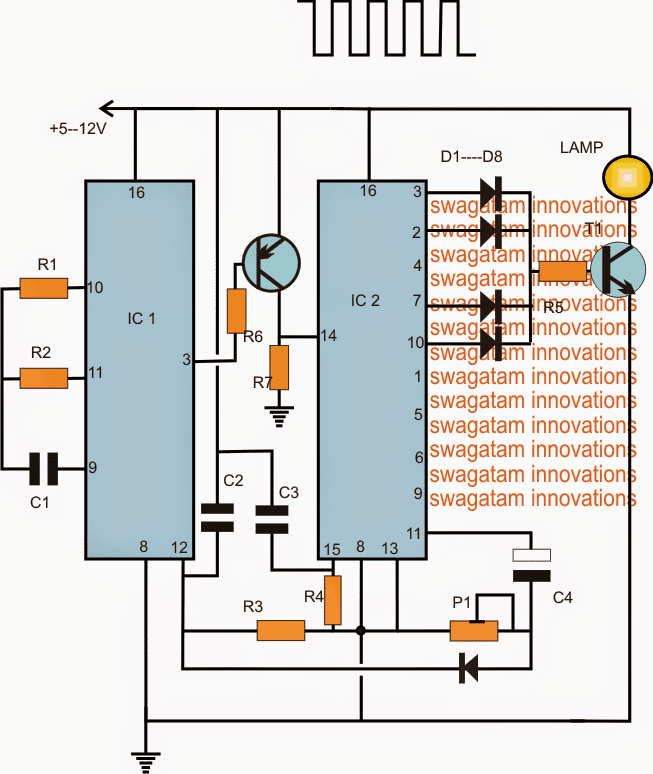
Parts list for the morse code lamp for lighthouse application
- R1 = TO BE CALCULATED
- R2, R3, R4, R6, R7 = 1M
- R5 = 1K
- P1 = 100K PRESET
- C1, C2, C3 = 0.22uF
- C4 = 10uF/25V
- D1---D8 = 1N4148
- T1 = 2N2222
- T2 = BC557
- IC1 = 4060
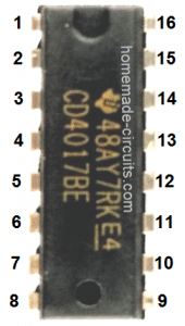
- IC2 = 4017
The Design
The proposed morse code light house lamp may be witnessed in the above diagram. The functioning may be understood with the following points:
IC1 4060 is set as a clock generator at some predetermined rate by appropriately selecting the value of R1. For implementing the specified sequence rate, this should be at the rate of 1/2 seconds at pin3 of the IC
The IC 4017 is wired in its usual sequential decade counter mode where its output pins respond with a momentary high with each clock applied at its pin14.
When the circuit is switched ON, capacitors C2, C3 reset the two ICs such that IC1 begins counting from zero and a logic low at its pin3, while IC2 also does the same by having its first pin3 high.
With pin3 high at the onset, T1 is switched ON which in turn switches ON the lamp.
After 1/2 second, pin3 of IC1 goes high, switching OFF T2 (PNP), this produces no effect on pin14 as it gets grounded via R7, pin3 continues to be ON until another 1/2 second.
During the next low from IC1, T2 gets switched ON and toggles pin14 of IC2 which forces IC2 to shift its pin3 high to pin2.
Since pin2 is also connected with T1, the lamp continues to be ON for another 1/2 + 1/2 second after which, the sequence is shifted to pin4 of IC2 (not shown). Since pin4 is not connected with T1, the lamp is now switched off until another 1/2 + 1/2 second that is for complete 1 second.
During the subsequent next 1/2+1/2+1/2+1/2 periods, the high jumps from the above mentioned pinouts to across pin7/10 switching ON the lamp yet again for 2 seconds.
Once the above time is elapsed, the high is now transferred across pins1,5,6,9,11. Pins1,5,6,9 together execute a delay of 4 seconds, however since this phase needs to have a delay of 7 seconds as per the request, P1 must be adjusted such that when the high appears at this pinout, the resetting of IC1 occurs for about 3 seconds which contributes to the total of 7 seconds.
After this the sequence is flipped back to pin3 of IC2 for repeating the course as per the above specified morse code rate.


Comments
Hi!
This is about just what I want, but my lighthouse needs two seconds on, two seconds off, two seconds on, two seconds off, two seconds on, ten seconds off.
Since it may be used live on an actual lighthouse it needs to be quite accurate, even in temperatures below -20°c.
Will a crystal oscillator work well in low temperatures, as you describe in your article about the 4060 circuit?
What would be the best way to control a lightsource that’s 24 volt with this circuit? I’m considering this to be able to use higher output led’s as lightsource.
Regards
Johan from Sweden
A crystal oscillator will be accurate, but I do not have much idea regarding the exact configuration and the associated calibrations. An easier idea would be to use a high watt resistor connected across the supply rails so that it heat up slightly and keeps the enclosed temperature at a reasonably warm conditions. The same could be achieved with a high watt LED positioned near the ICs.
The circuit requested by you will require an additional 4017 included in the existing design, will try to update it soon, if feasible.
Thank you!
I appreciate it.
The three LEDs would operate as one unit…all flash or fade together.
I’ll try if possible…
Hi Swagatam,
I was studying this circuit to try to create a similar circuit and I noticed a typo. In paragraph 6 “After 1/2 second, pin 3 of IC2 goes high, switching OFF T2,……….” should read, pin 3 of IC1 goes high, switching OFF T2,……
I am trying to create a circuit that lights three LEDs (red, white, blue) (with very slow fade in and fade out) for 1 clock pulse and then is off for one clock pulse and then lights the three LEDs by flashing them for the next clock pulse and then is off and then lights the three LEDs with a double flash for the next clock pulse and then resets to continue. I don’t want to use a micro controller. Is this possible? Would this be interesting enough for you to design a circuit? Thanks!
Thank you Norman, I have corrected the text according your suggestion.
Are those 3 LEDs required to be switched together or one by one?
In air traffic control towers, signal lamps are still used today, as a backup device in case of a complete failure of an aircraft’s radio. Light signals can be green, red, or white, and steady or flashing. Messages are limited to a handful of basic instructions (e.g., “land”, “stop”, etc.); they are not intended to be used for transmitting messages in Morse code. Aircraft can acknowledge signals by rocking their wings or flashing their landing lights .
Thanks for sharing the info, appreciate i!