If you are not too keen in understanding the deep technical aspects of a true sine wave power inverter, yet want to build it within a couple of hours, then this article will help you to accomplish it using an audio power amplifier and some DC motors. Here we'll how to convert audio amplifiers into pure sine wave inverters
- Design#1
- Basic Working Principle of Inverters
- Using DC motors for generating Sine Signal instead of PWM circuits
- Parts Required
- Design#2: Using a 100 watt Amplifier Module
- The Oscillator Circuit
- Parts List
- The Current Amplifier Circuit
- Construction Hints
- Design#3: 500 W Pure Sine Wave Inverter
- The Sine wave Generator
- Using a Power Amplifier Circuit as an Inverter
We will consider 3 separate true sine wave inverter designs using appropriately dimensioned audio amplifiers, and digital sine wave generator circuits
Design#1
Let's begin by understanding how a couple of small DC motors can be used for generating pure sine wave signals and then proceed with the details of coupling the motors with a ready made power amplifier for acquiring the desired AC mains true sine wave power output. In this article I have explained an innovative idea of configuring a few ready made units like a power amplifier, a couple of DC motors and a battery into a sine wave power inverter.
There are folks whose lives depend on the power accessed from inverters and for them these gadgets are truly priceless and crucial. There are also individuals who intend to own inverters but are too ill informed regarding their technical specs etc and therefore are reluctant in bringing them home.
Another factor with inverters is that they can be immensely expensive, especially the ones which can be operated universally with all types of electrical appliances or simply the true sine wave inverters. I have already discussed many inverter circuit diagrams here ranging from the most ordinary hobby type idea to the very sophisticated modified sine wave and the true sine wave inverter types. However these designs are all too technical and definitely not meant for the layman.
The ideas explained are not simple and require prior expertise with electronics to understand them, and also a thorough knowledge regarding practical electronics to build them.So does it mean a lay man would be unable to understand these magnificent power houses? And does it mean that a layman is not entitled to enjoy the benefits of a homemade sine wave power inverter, which can be not only lot of fun to build but also very cheap and reliable as compared to the commercial counterparts.
The following section will clearly show how a sophisticated true sine wave inverter can be built by virtually anybody having ordinary technical skills and knowledge.
The idea I have explained below is not a circuit based unit which needs assembly using PCBs, electronic components etc. rather here we buy ready made units like amplifiers, motors, batteries, transformers etc. and integrate all these for constructing the final piece. Let’s learn how it can be done within an hour.
WARNING: THE CONCEPT IS ONLY ASSUMED BY THE AUTHOR AND HAS NEVER BEEN CHECKED OR VERIFIED PRACTICALLY, BUILD IT AT YOUR OWN RISK AND IF YOU HAVE SUFFICIENT FAITH ON THE FEASIBLITY OF THE EXPLAINED CONTENT.
Basic Working Principle of Inverters
The Concept: Inverters as we all know are nothing but voltage amplifiers or steppers. The best known method of stepping up voltages is through transformers where isolated winding are used for achieving staggering voltage level multiplications. Basically the process takes place through magnetic inductions for transforming high current fluxes to high voltage outputs.
To comply with the above process, a high AC input is required which can be stuffed into the relevant winding of the transformer for getting the desired 230 or 120 volt AC power.
However since the whole purpose is to convert a DC source to mains levels, we first have to convert the low level DC to the low AC input. In square wave inverters this is easily achieved by using ordinary astable circuits, but a square wave output is what we are absolutely not looking for, so how do we actually “manufacture” a true or pure sine wave input for our prototype.
Using DC motors for generating Sine Signal instead of PWM circuits
Off course we can do it using complex opamp circuits like a “bubba” circuit, but since here we don’t want to involve much of electronics, a simpler solution would be to use a small DC motor for the purpose.A motor as we all know can be rotated by applying power to it, the rotations are caused by constant twisting interaction of the permanent magnet and the induced electromagnetic effect.
If we reverse the process, that i.e. if we rotate a motor by applying external mechanical force, we can induce a fair amount of varying potential across its winding terminals and the received voltage will have an sinusoidal wave form. The waveform will be perfectly natural and a true sine wave.
If this sine wave input is amplified to the desired levels, then perhaps our mission can be simply accomplished. Instead of embarking on complex mosfet circuits meant for inverter applications, I thought it was a better idea to feed the above sine input to a high power audio amplifier procured ready made from the market.
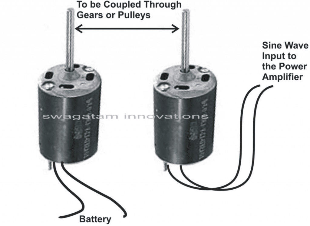
One such sample amplifier model is shown here. The outputs which are meant to be joined to speakers must be joined with our power transformers.
If the amplifier is a stereo then we can use a pair of transformers and terminate the AC outputs of the transformers to separate AC outlets so that different appliances can be connected to them.
The motor which actually manufactures the sine waves is driven by another motor attached with pulley/belt mechanism. The driving motor is operated with the available battery power.
Parts Required
You will require the following parts and units for the making this true sine wave inverter:
A ready made high power audio amplifier
Transformer – Rating should match with the power of the amplifier. If the amplifier can deliver 500 watts at 50 volts, it means the input winding of the transformer must be rated at 50 volts and 10 Amps.
Alternatively the power amplifier’s power supply transformer can be removed and used for the purpose.
Motors – The RPM must be above 3000 and should be adjusted to exactly 3000 RPM so that a 50 z frequency can be achieved from it.
Suitable cabinet for accommodating the whole assembly.
Nut, bolts, washers, wires, battery etc.
Wiring Layout for the Proposed Sinewave Inverter using an Audio Amplifier

How to Assemble the Audio Amplifier with Battery and Sine Input
It’s quite simple and all about integrating the procured units as per the given diagram. The whole system along with the amplifier, transformer and the motors may be housed inside a bigger metal cabinet and fixed appropriately.
The motors especially must be tightly clamped with the base of the inverter cabinet to avoid vibrations and noise. The cabinet must also include all the terminals specified with the unit, fixed externally for the battery connection and the AC outlets.
Through a simple concept, the idea of building a pure sine wave inverter has been explained in the article. Read on to know the whole construction details.
Design#2: Using a 100 watt Amplifier Module
It’s understandable that sine wave inverters are not easy to build, due to many different reasons. But it’s probably the most sort after circuit and also pretty difficult to find. For the folks who are desperately looking for such a circuit, perhaps this article can help.
After a lot of thinking, I probably seem to have designed an easier (though not quite efficient) concept of a pure sine wave inverter circuit. Since the circuit has not been tested by me so won’t be able to tell much regarding the exact specifications of the circuit and would like to leave it up to the readers to decide the feasibility of the present circuit.
The idea struck me while reading the circuit description of a MOSFET audio amplifier. We all know that when an audio signal is fed at the input of an amplifier, it produces an amplified output power having exactly the same properties as the input.
That simply implies, in place of an audio signal if a pure AC signal say from a Wien bridge circuit is applied to the input of a power amplifier and an inverter transformer connected to its output (where normally a speaker would be connected), it would certainly produce an amplified replica of the input. And the secondary winding of the connected inverter transformer would definitely produce a sine wave AC power (My assumption).
The only big problem is the loss of a significant amount of battery power in the form of heat through the power devices reducing the overall efficiency of the inverter.
Let’s move on and see how the different stages of the proposed circuitt functions.
The Oscillator Circuit
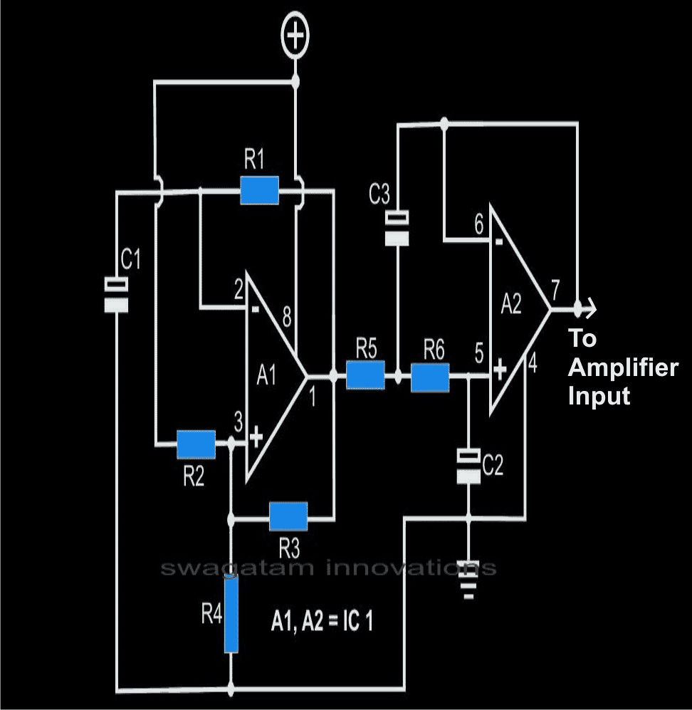
The simple sine wave generator circuit shown alongside may be used to produce the required sine waves at the input of the power amplifier, let’s study regarding its functioning through the following steps:
Op amp A1 is basically wired as an astable multivibrator,
Resistor R1 and the capacitor C1 define the frequency of oscillation of the astable.
The square wave from A1 is fed to A2 which is configured as a double pole low pass filter and is used to filter out the harmonics from A1.
The output from A2 will be almost a pure sine wave, the peak will obviously be dependent on the supply voltage and on the type of the opamp used.
The frequency of the present circuit has been fixed to approximately 50 Hz. If the values of parts shown in the parenthesis are selected, the frequency will be around 60 Hz.
Parts List
All resistors are 1/8 watts, 1%, MFR
R1 = 14K3 (12K1),
R2, R3, R4, R7, R8 = 1K,
R5, R6 = 2K2 (1K9),
R9 = 20K
C1, C2 = 1µF, TANT.
C3 = 2µF, TANT (TWO 1µF IN PARALLEL)
C4, C6, C7 = 2µ2/25V,
C5 = 100µ/50v,
C8 = 22µF/25V
A1, A2 = TL 072
IC2 = LM3886 (National Semiconductor),
HEATSINK FOR IC2 AS SHOWN IN THE IMAGE,
TRANSFORMER = 0 – 24 V/8 AMPS. OUTPUT – 120/230 V AC
PCB = GENERAL PURPOSE
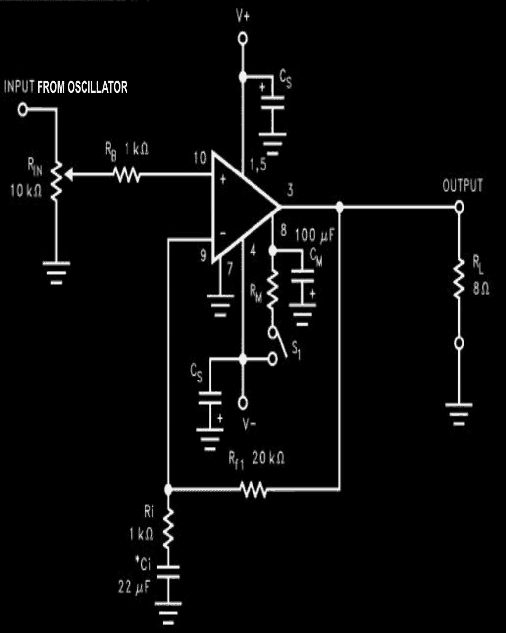
The Current Amplifier Circuit
In view of keeping the design specifications very simple, and the component count as minimum as possible, a single chip amplifier was the basic requirement. A reasonably powerful amplifier using IC LM3886 (National Semiconductor) was ultimately selected by me for the purpose. The salient features of this power amplifier chip are as follows:
Truly versatile and a high performance IC compared to the other types of hybrid and discrete devices.
Totally internally protected from instantaneous peak temperatures,
Has got a dynamically protected safe area of operation,
The out put is perfectly shielded against a short circuit with the ground or the positive supply through an internal current limiting circuit network.
The output is also protected against output over voltages due to inductive load transients,
Can be operated with voltages as low as 20 volts up to a staggering 94 volts.
Its technical specifications are as follows:
Input sensitivity is 1 Vrms
Output power will be in the vicinity of 100 watts if the transformer primary resistance is around 4 Ohms.
Power bandwidth is a massive 10 Hz to 100 KHz.
Construction Hints
The circuit basically consists of just two ICs as the main active components and a handful of other passive components, so the construction procedure should be very easy. The whole assembly may be simply done over a piece of general purpose board (approximately 4 by 4 inches).
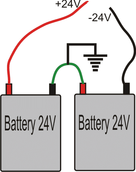
IC2 should be positioned at the edge of the PCB to facilitate easy fitting of the heat sink. The present utilizes two large 24 volt truck batteries. Connect them as shown in the diagram.
A separate battery charger is required to charge the batteries.
Design#3: 500 W Pure Sine Wave Inverter
In this post I have explained how to make a 500 watt pure pure sine wave inverter using a 500 wat audio amplifier to get reasonably outstanding results.
The circuit basically uses a push pull topology through a couple of 24V batteries. The use of two 24V batteries allows lower AH batteries to be incorporated with higher efficiency and wattage.
12V batteries can be also tried however the power output would be reduced to half.
Since a dual supply is used the connected transformer does not need to be a center tapped type, rather a two wire ordinary transformer becomes suitable here.
The couple of designs shown below are all that would be required for implementing this simple pure sine wave inverter circuit.
The Sine wave Generator
The first circuit is the basic sine wave generator which becomes the feeding input to the main sine wave amplifier or the output stage.
The sine wave generator produces a pure sine wave output with the shown components at about 50Hz, for other frequencies the 2.5K resistor may be altered, and tested in a simulator for fixing the desired results.
The sine generator circuit should be supplied with +/-12V, and not directly from the 24V battery supply as that might damage the IC permanently.
The opamps used in this sine generator are from the IC TL072
Using a Power Amplifier Circuit as an Inverter
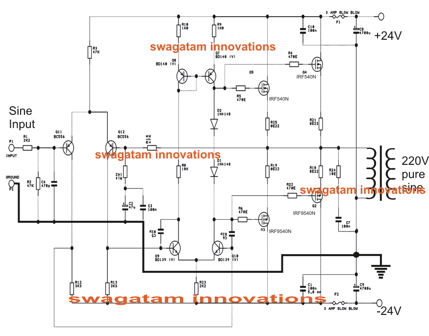
The next diagram shows the output stage of the proposed simple pure sine wave inverter circuit which is actually a 500 watt power amplifier design. As can be seen the design is not at all complicated.
All the involved components are standard, and easily available.
The mosfets are IRF540n and IRF9540n which complement each other to produce the required push pull effect over the attached transformer.
With a 0-24V/25amp transformer, and a couple of 24V batteries the circuit would be able to generate as high as 600 watts of pure sine wave output at the relevant voltage.
The output across the right hand side opamp of the sine generator is to be connected across the input of the second circuit for initializing the proposed operations.
Battery Wiring Details for the above Simple Sine Wave Inverter Circuit
Want to do an H bridge inverter with 50hz igbt and need your help and technical advice with schematics please.
You can try one of the designs mentioned in the following article:
https://www.homemade-circuits.com/simplest-full-bridge-inverter-circuit/
I mean which terminal am i suppose to hook the sinodial input???
The amplifier will have a music input socket, you must feed the sine wave into that socket.
Where do i feed the sinwave through??
At the points where the music input is fed to the amplifier
Thanks to you sir
The output of a DC motor will be DC just like the input. It cannot be used to generate AC waveforms. An AC motor is needed, but using two coupled motors will however require quite a lot of electronics to keep the rpms and therefore the frequency constant. Wrong or varying frequency may cause all kinds of problem with devices that are powered by this inverter.
An electronic signal generator will be much simpler and more stable in operation.
I agree with you, an electronic signal generator would be a much better option.
I had a thought that popped in my head which caused the search that finally led me here, and thank god for that, I’m so pissed off that searching the internet has become so annoying because of all the stupid searches people make but anyway. I was thinking about a car audio amp as inverter. Hook 12v power and jump remote wire to power on, and use the rca jacks as an input signal and get your ac output directly from the speaker output which ac power. I know there has to be something wrong with my idea but how close to possible am I thank you for your time
Very impressed by your idea of using amplifier for people like me who would want to make sine wave inverter without knowing too much of technical aspects. I have a question – instead of motors can i use EGS002 board for generating sine wave and feed to audio amplifier ( I will ignore mosfet driver section of EGS002 board ). This way – I have to just integrated EGS002, amplifier board and Transformer .
Thanks
Thank you and glad you found the concept interesting. You can use any suitable sinewave frequency, instead of the motor assembly which is actually not a practicable approach. You can even use an SPWM generator for getting the very same results at the transformer output.
Pls which of your inverter circuit can be used to make 100kva inverter.How can I construct it?
I have used audio amplifiers to drive both ac and DC Motors with music. By adjusting the highs and lows one can reverse a dc motor somewhat like a pwm with a reversal switch, and in ac Motors you can change the speed by using a tone generator with varying frequency controls. EDM gives fun results.
Your information is very easy to learn thank you so much sir
It’s my pleasure shashidhara!
Hello sir myself Abhi
I have an inverter circuit of 100watts and input is from battery 12v 7amp but the question is when I try to glow a bulb initially it glows continues but after an hour it starts blinking and transformer is 12 0 12 and 1amp wt can I do to that problem
Hello sir myself Abhi
I have an inverter circuit of 100watts and input is from battery 12v 7amp but the question is when I try to glow a bulb initially it glows continues but after an hour it starts blinking and transformer is 12 0 12 and 1amp wt can I do to that problem
Hi Abhi, it could be happening either due to the battery getting too much discharged or the power devices getting very hot.
make sure that the power devices are mounted on large heatsinks…also make sure that the transformer too remains cool while operating.
Use a 555 timer to create a 60hz sinewave instead of the motor.
Hello swagatam sir can you please post a 5.1 audio amplifier circuit using tda1554 ic and including subwoofer circuit. And i am fan of your work.thank you
Hi JE, you can try the following circuit
https://www.homemade-circuits.com/2012/08/exploring-ic-tda-7560-4-x-45w-quad.html
or the following one
https://www.homemade-circuits.com/2016/06/simple-surround-sound-decoder-circuit.html
Thanks sir
Sry to bother you but can i use a motor based sine generator to feed sine input to above 1000w inverter circuit given in your link
yes that's possible
Can we apply the amplified sine wave output from amplifier to MOSFETs connected in push pull manner and a transformer connected to MOSFETs so we can get sinewave ac output and also we can increase the no of mosfet and size of Transformer to get desired level of power output
that's not required because the amplifier is already doing this for you….the amplifier already has mosfets inside.
alternatively you can do it in the following manner
https://www.homemade-circuits.com/2012/05/make-this-1kva-1000-watts-pure-sine.html
You can use your smartphone as signal generator Nice blog ive also think that idea
Why not use a sine wave stored/played back on an mp3 player? It is basically an audio signal after all. No need for motors/oscillators if you don't have access to them. We all have access to mp3 players. I understand the length of the audio file will be an issue, but my guess is that a single sine wave source will be easily compressed by the mp3 format. Infact, Lossless compression may do an excellent job of signicicantly reducing the file size of say a 24 hour audio sample of a 50hz sinewave? Audacity can generate these signals quite easily. I will experiment with this. Thanks for posting this project! very interesting indeed!!
MP3 player can be an option but can be costlier and bulky, there are easier options available for generating a sample sine wave, as shown in the following article:
https://www.homemade-circuits.com/2014/12/3-phase-signal-generator-using.html
Good day I have a Starsound Digital SS1D-7800 7800w Monoblock Amplifier I would like to make a inveter out of it can I use the same oscillation circuit shown to generate sine wave.
Good day, yes you can try it, or alternatively you can make use of an electronic sine wave generator circuit at the input of the amplifier, as given below:
https://www.homemade-circuits.com/2014/12/3-phase-signal-generator-using.html
Just remember that you won't get 7800watts of power out of the amp. You will only be able to draw off the rms output which is probably around 1500w-2500w or so, depending on the impedance of the transformer you use.
tnx wil giv it a try afta school exams tnx alot
but my amp is a powered with dual power supply how wil i go abt that? thank you
use the last circuit as it is, just procure another battery…connect its negative with the existing battery's positive, now connect amp positive with this new battery positive and connect the ground of the amp with the center link of the two batteries….the amp negative finally can be connected to the shown negative of the earlier battery.
the motor connection should not be changed.
wow love dis.pls am i going to power the amplifer or i wl jst send signal from the motor to the input of the amp?
see the last diagram you'll need to wire it exactly as shown in the diagram.
Dear,
My project is to build a single phase sine wave inverter system for my house upto 350 watts.
so i was looking out for a technique which could just give out a sine wave signal.
in my previous comment, all experiments that i performed was just to get the sine wave signal from the step.motor, i did all possible checks and confirmed the clarity of the sine signal using an ordinary speaker, it was perfectly good confirming everything properly.
Now, the way how i wish to prepare the inverter system is as below;
1. i will first generate the sine wave signal using the step.motor by spinning it with the help of a brushless dc motor. the outputs that i will take out from the step.motor are one phase and ground. i will the connect ground of step.motor to gnd of bldc motor i.e., minus to minus.
(minus of all polarised devices will be connected together to avoid wiring confusion)
2. next, i will connect the signal wire that is the phase wire from the bldc motor to an IC either 555, 4047 or any other IC via or not using resistance.
OR may be if i have to amplify the signal output from the bldc using a small signal fet like 2n7000 or so, i will go ahead and give the output from drain to the IC via resistance.(connections will be done only after confirming frequency from bldc phase point or output from mosfet drain after drain resistor is 50Hz)
3. Now being the fundamental waveform of switching ics a square wave, i thought that i could feed the above sine signal to some pin on the ic which can facilitate an 'input signal connection'. i can then bifurcate this input signal into one or two output signals by using an IC.
4. in this way i can get a sinewave output signal from the IC output pins, eg pin3 of 555 or pin10,11 or 13 of 4047.
5. next i will connect output signal from the IC to power devices(via resistors) either mosfets or transistors or both in order to further amplify output before it is sent to transformer(final power device).
6. input to transformer will be center tapped or 2 wire system, i will attach a safety fuse to either of them i decide to use, keeping one wire of trafo. input go to battery positive.
Now, this inverter system is ready according to my part of knowledge, guide me if this system of building this inverter is correct according to me, please let me know if i need to make any changing anywhere.
I hope to hear the best from you.
Regards,
Thanks.
Sherwin, your 1), 2), and 3) assumptions will not work…ICs neither accept nor produce sinewaves….and moreover fets absolutely won't reproduce sine waves if their gates are driven with sinewaves.
generating sine wave is not a difficult job, amplifying is.
that's the reason using an audio amp is recommended in the above article….and not the regular inverter topology.
Dear,
i'm back to this blog of the sine wave generation system through use of motors, though i'm impressed with this technique
i would describe my experiments as follows;
1. i purchased a second hand dvd drive from the market and hacked off the stepper motor from it, knowing that i could generate a sine wave from it.
2. the motor had 3 wires connected, the schematic of the motor was a 'wye' configuration, the center point of the y config. was soldered and pulled down between the cogs, kept short but had no connection on pcb. all this was upon careful inspection.
3. i studied the hum of the sine wave from the computer. it was something like a 'booooooooo' sound from my speaker unit, i heard the frequency signals from 50 to 500Hz and confirmed it properly.
4. i had a speaker hacked off an old radio and connected it to the motor terminals, the only connection i could do was from phase to phase since i didn't have access to the center common wire.
5. i drove the stepper using a 12v printer motor, its tip correctly sat on the steppers' head. i held the motor vertical on the stepper seeing it spin properly, i noted the sound from the speaker it was a similar sine hum quiet clear and precise.
6. next, i connected a small 5mm clear red led at the motor terminals but it didn't light up. i then connected a small step down transformer in reverse and led lit up, getting to know that current was very small at the motor o/p terminals.
now i want to know that how to amplify the current from the steppers' output?
Thanks and please help.
Dear, Although I could not understand what you are trying to experiment, what you did using a transformer was the right method of boosting current, that is by stepping down the voltage with an inductor….there's no other easy way of implementing this….
App store can provide you the Sine Wave as Signal Generator, just install this App to your iPhone. Enjoin.
its a great blog i have a question here we talk about power loss a simple inverter vs audio amplifier
which is most efficent btw thanks for the post
thanks!
if a PWM input is used the efficiency of an audio amplifier could be as good as a standard inverter.