The following multi-function water level controller circuit post is based on the suggestions expressed by Mr. Usman. I have explained more about the requested modifications and the circuit details.
The Circuit Suggestion:
The concept of this circuit looks good. May I suggest a couple of other desirable features?
1) To protect the motor from potential overheating (or as a safety feature) can u add an automatic shutdown timer? If the motor is running for one hour (or 1.5hrs or 2-hrs) and the water level does NOT reach the level-sensor, the motor should be automatically stopped. Of course, it can be re-started manually by pushing the start button again.
2) Can the motor be manually stopped at any time? For example, what if one wants to water the lawn (or wash the car) for a few minutes using high pressure water directly from the motor?"
Thanks very much!
Your suggestions are interesting!
I think I have discussed these issues in this article.
However instead of a timer I have used a temperature sensor circuit for tripping the motor if it starts getting hot.
The motor can be manually stopped by shorting the base of T3 to ground. This can be done by adding a push button across these terminals.
So the upper push button may be used for initiating the motor while the lower button may be used for stopping the motor manually.
Thanks Swagatam for a prompt reply. I've found another circuit on your blog (April 20th post) that is closer to what I have in mind.
I want a slightly different control logic in the above circuit:
Motor START Logic:
Manual push button (already implemented)
Motor STOP Logic:
1) Water level reaches a pre-determined level (as implemented in April 21st post), OR
2) A pre-determined time has lapsed (e.g. 30, 60 or 90 mins, this requires a long time-delay/counter), OR
3) Manual stop (manual override), OR
4) Power faliure (load shedding), this is implemented by default!
So I guess, the STOP logic (1, 2 and 3) can be configured to the base of T1 (in your April 20 post) and it should work. Pls comment, and if you have time maybe you can make a new post!
Thanks
Usman
The Design:
Let's analyze the above requirements and check how they have been implemented in the following diagram:
1) Water level reaches a pre-determined level: Point A and B may be appropriately fixed inside the tank for regulating this function.
Since point B is situated at the bottom of the tank, remains connected with the water permanently, now as the level rises and comes in contact with point A, the positive potential from point A connects with point B, which instantly reset pin#12 of the IC, switching OFF the relay and the entire system.
2) A predetermined time has lapsed: This feature is already present in the below given circuit. The timing outputs can be increased to any desired extents simply by increasing the values of P1 and C1.
3) Manual stop (manual override): This feature is actuated by SW2, pressing which resets the IC pin#12 and the entire circuit.
4) Power failure (load shedding): During a possible power failure or instantaneous power "blinks", the IC needs to be supplied with the required supply voltage so that the timing does not get interrupted. This is very simply done by adding a 9 volt battery to the circuit.
As long as normal power is present, the cathode of D3 stays high keeping the battery switched OFF from the circuit.
The moment power fails, the cathode of D3 becomes low, providing a way-in to the battery power which smoothly replaces the supply to the IC without causing any "hiccup" to the counting operation of the IC.
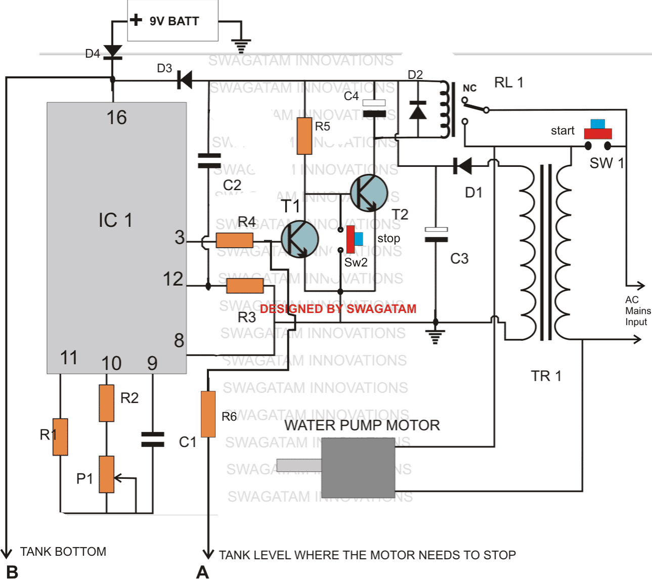
Parts list for the above explained multi-function water level controller circuit
All resistors are 1/4 watt 5%
- R1, R3= 1M,
- R2, R6 = 4K7
- R4 = 120K
- R5 = 22K
- P1 = 1M preset horizontal
- C1 = 0.47uF
- C2 = 0.22uF disc ceramic
- C3 = 1000uF/25VC4 = 100uF/25V
- D1, D2, D3, D4 = 1N4007,
- Relay = 12V/SPDT
- SW1,SW2 = Bell push type of button
- IC1 = 4060
- T1, T2 = BC547
- TR1 = 0-12V/500mA
- BATT - 9V, PP3
Water level buzzer indicator circuit
The following circuit of a water high level and low level indicator circuit was requested by Mr.Amit. Please read the comments given below to know regarding the exact specs of the requested circuit.
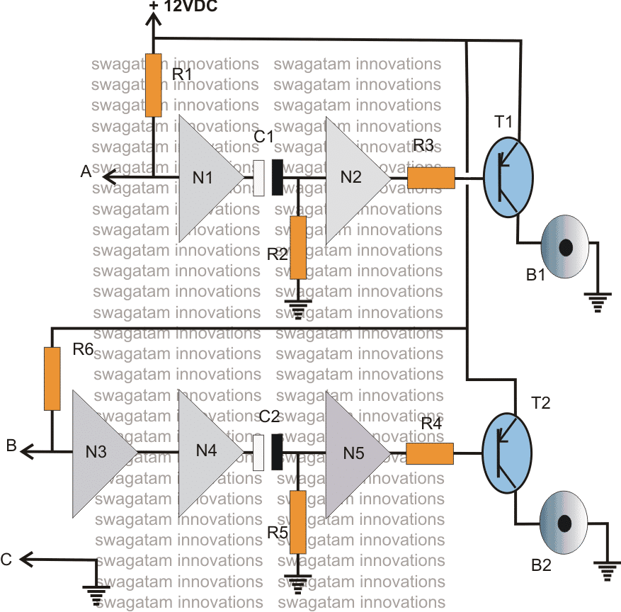
Circuit Operation
The above shown water high and low level buzzer indicator circuit may be understood with the following points:
Point C which is connected to the ground or negative of the supply rail is kept immersed in the tank water at the bottom level such that the water present in the tank is always held a logic low.
Point B is the low level sensor point which must be positioned near the bottom of the tank, distance may be set as desired by the user.
Point A is the high level sensor, which should be held somewhere at the top of the tank as per user preference.
When the water level reaches under the point B, point B goes high due to R6, making the output of N4 high and consequently producing a low at the output of N5....the buzzer B2 starts buzzing.
However in the meantime C2 starts charging up and once it's fully charged inhibits the positive potential at the input of N5.....the buzzer is switched OFF. The time for which the buzzer remains On may be determined by the values of C2 and R5.
In an event the water reaches the top level of the tank, point A comes in contact with the low logic from the water, output of N1 becomes high and the same process is repeated as explained above. However this time B1 starts beeping, only until C1 gets fully charged.
Five gates from the IC 4049 have been utilized here, the remaining one unused gate input should be grounded for maintaining stability of the IC.
Parts List
- R1,R6 = 3M3
- R3,R4 = 10K
- T1, T2 = 8550, or 187, or 2N2907 or similar
- C1,R2 = to be selected for setting up buzzer on time
- C2,R5 = to be selected for setting up buzzer on time.
- N1---N5 = IC 4049
- B1,B2 = Loud piezo buzzers


Comments
Hi Swagatam,
You are having one of the best blogs which hits the nail right at the head. I am trying to make a water level indicator, but with data logging to an SD card to collect some data for research. I just wanted some advice on sensors. I would like to have some kind of sensors which won't corrode easily. Whats your experience with these stainless steel or brass probes or what other alternatives do you suggest. I was also thinking of using ultrasonic distance sensor, but again I am worried that it might also corrode due to humidity in the tank. What do you say ?
Regards
Raman
i make a water level monitor using a remote controlled toy car circuit.
It can can monitor water levels and alarm when tank is full.But i can't to controll the motor
Pls help me?
show me the full details, i'll check it.