Due to some reason if the loudspeaker of a power amplifier gets shorted, that may lead to a fatal damage to the amplifier component. To prevent this an amplifier short circuit protector circuit can be very useful.
In the following post I have explained 2 simple amplifier short circuit or overload protection circuits for safeguarding amplifiers from burning.
Why we need a Short Circuit Protection
While working with high power amplifier designs, two things become crucial, the protection of the amplifier and the protection of the speakers from an accidental over current influx.
Especially when the amplifier design involves costly mosfets, the design becomes specifically vulnerable to short circuits at the outputs. A short circuit at the output may be caused due to mishandling or ignorance from the part of the user.
Whatever might be the reason, the end results in the destruction of the precious MOSFETs inside the amplifier box.
The above mishap can be prevented by adding a small circuit for detecting a short circuit conditions at the outputs of an amplifier.
Circuit Operation
The given amplifier short/overload protection circuit diagram, shows an inexpensive design using just a single transistor for implementing the intended feature.
Normally a low value resistor is usually employed at the output of mosfet amplifiers, the current developed across this resistor can be well exploited for tripping a relay in case it exceeds the safe maximum current value.
The current threshold across the above resistor is sensed by an LED inside an optocoupler, which lights up the moment a short or overload conditions is sensed.
This instantly triggers the opto transistor which in turn switches ON the transistor driver and the associated relay mechanism.
Since the relay coils support the amplifier connection with the speaker output, disconnects the amplifier from the output connection, preventing the amplifier devices from a possible damage.
The capacitor at the base of the transistor keeps the transistor switched for a few seconds so that the relay does not oscillate randomly.
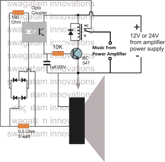
The efficacy of the above can be further increased, if the relay driver transistor is replaced by an SCR as shown below:
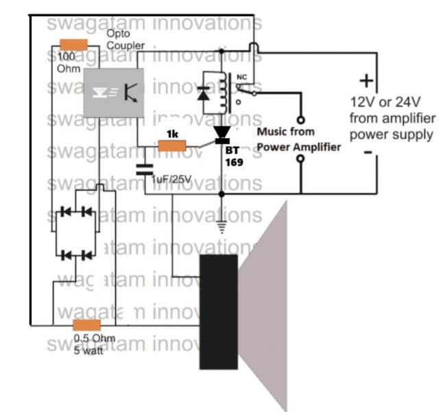
To get the pinout details of BT169, you can refer to this article.
The next simple short circuit and overload protector design presented here can be used for protecting valuable mains operated gadgets like amplifiers, TV sets, DVD players or any other similar appliance. The circuit was requested by Mr. Ashish.
Technical Specifications:
I really found very very useful circuits in your blog and I have tried most of it , Thanks for that .
I have made a 150 Watt Mosfet Stereo Amplifier and I was searching for a good, simple short circuit protection circuit for this amp , I only found protection circuit for speakers in your blog and I have added it .
I wanted a simple low cost Short circuit protection circuit after the rectification stage to protect sensitive Mosfets and costly transformer . I thought you would help , Thank you
My amplifier runs at +/- 36 V and I really needed it as I live near a village where there is lot of Power problems . Can you help ????
The Design
Normally all sophisticated gadgets today incorporate an in built short circuit protector arrangement, yet still adding a more comprehensive external protection device could only benefit the connected system.
Moreover, for gadgets such as amplifiers which are home built this protection device could prove to be very effective and useful. Also for an hobbyist who prefers building electronic gadgets at home could be greatly benefited with the present idea.
The presented short circuit protector design works on a very basic principle and costs not more than a couple of dollars.
I have explained the functioning details of the proposed circuit.
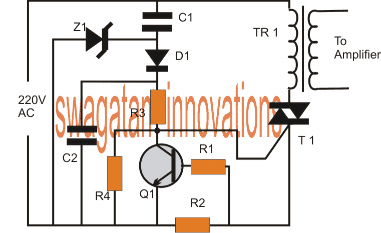
On applying power, the high current from the 220V input is dropped sufficiently by C1, rectified by D1 and filtered by C2 to feed the gate of the triac T1.
The triac conducts and switches ON the connected transformer primary thus switching ON the load which in this case is a power amplifier.
The transistor Q1 along with R1, R2 forms a current sensor stage.
R2 specifically is chosen such that it develops adequate voltage across itself at the specified dangerous high current threshold.
As usual the formula for determining R2 = 0.6/current(A)
As soon as the triggering voltage accumulates across R2, Q1 activates and sinks the gate voltage of the triac to ground making it switch off.
The regulation continues as long as the short or overload condition is not removed.
The above short circuit regulation ensures that the current level above the specified dangerous level is restricted safeguarding the precious devices associated with the connected amplifier.
If a latching feature is required for the above design, the emitter Q1 can be configured with an SCR and the SCR can be used for latching and switching off the triac.
Circuit Diagram
Parts List
- R1 = 100 ohms
- R2 = see text
- R3 = 1k
- R4 = 10k
- C1 = 0.33/400V
- C2 = 1uf/250V
- Q1 = BC547
- Z1 = 12V/1 watt zener diode
- T1 = BT136 or as per current rating
- TR1 = As per load requirement specs.
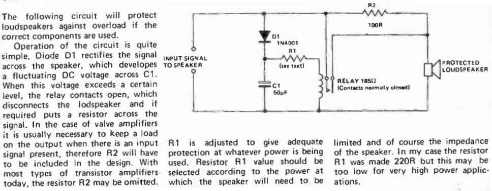
Relay Delay Loudspeaker Protection
Another simplified version of a relay delay timer for protection the loudspeaker from initial switch ON surge can eb seen in the following diagram:



Discussion & Solutions
Hi,
yes by mistake the positive connection is not shown in the diagram, a separate +12V should be connected to the link that connects the relay coil and the opto transistor.
not tested, but i am sure about it.
yes it would also handle DC shorts across the speaker
thank,,, its usefull
Useful but I want the number of opto couple
OK it is useful circuit I want to know the number of opto couple
Thank-you
use 4n35 optocoupler
Say the value of resistance 0.5 ohm iam not able to get in india
use 5nos of 0.1 in parallel
Sir thank you for reply but in India only 1 omhs is available can I use that one
Thanks again
saravanan, please tell what is the max wattage limit do you prefer to implement? the resistor value will depend on this
Can I use MCT2E instead of 4N35
yes you can!
100 Watts 5.1 amplifier system it is designed by MOSFET IC I have changed my speaker for more than 8 times in 2 years
Thankyou
for 100 watt you can use the following formula
100/V = current
therefore R = 1.5/current
here V is your amp supply voltage
Sorry I can't understand which voltage
Input to transformer is 220 volt and the output of the transformer is 24 volt the transformer current rateing is 5 amps
Mean while I get only 1 ohmes in India
Thank-you
the 0.5 ohm shown in the diagram will need to be calculated as explained using the formula in the previous comment.
If your amplifier operating volatge is 24V then
100/24 = 4.16
R = 1.5/4.16 = 0.36 ohms
wattage of resistor will be = 1.5 x 4.16 = 6.24 or a 10 watt will do.
if you are getting 1 ohm then use two in parallel, in place of the indicated 0.5 ohm
…..two 1 ohm in parallel will do in place of 0.36 ohm
Thank you sir so I want to ready 6 circuit for 5.1 amplifier
you are welcome, yes that's right!
This circuit is new it OK can we use in4148 diode
What is number of diodes
use 1N4007
Thank g
Does anyone have a COMPLETE working circuit (including missing +12V to relay and opto) with all parts IDENTIFIED? Has anyone tested or built this circuit?
Sir,
This circuit also prevent DC from amplifiers O/P? means, this circuit act as a speaker protection circuit?..
How can calculate The resistor value in +75v -0- -75v 250W amplifier?
Rahul, yes you are correct, it will protect speaker from burning.
for 75V 250 watt, the current limiter resistor can be calculated as
250/75 = 3.33 amps
R = 2/3.33 = 0.6 ohms
watt = 2 x 3.33 = 6.66 or 10 watts
circuit NOT WORKING . . .
find the fault in your design, it will work
only detects DC at speaker out but not detects SHORT at speaker out…. optocoupler needs DC supply in order to work… how…in this circuit provides a SHORT protection, let’s say a faulty (shorted)speaker wire to the amplifier?
did you check how much voltage is generated across the sensing resistor during the intended overload? did you check whether that voltage was actually sufficient or not for triggering the opto LED?
the bridge is already present to convert the pulsating DC into rectified DC?
check all the parameters above, and set up the resistor accordingly as per your overload threshold, the circuit will cut off the relay at the set point
Hi sir …IAM planning to build your design what is the computation for my power amp are 1000 watts at 80 volt ….t.y.
Dondon, I have explained the formula in the article, please do it according to it…
Thank you sir …I figure it out and calculate the exact value of the resistor…..t.y…
Hi! Nice circuit. How do you decide to use 1.5 or 2 in the above formulas? That number means the voltage drop in the resistor to trigger the diode bridge. Thanks
Hi, thanks, I am glad you liked it! for the opto coupler to conduct optimally the current limiter resistor must develop a voltage equal to the sum of the forward voltages of two series diodes from the bridge and the LED inside the opto….the total may reach upto 2V minimum, that’s why the value 2 needs to be used in the formula.
Hello brother my name is sandeep from Kerala,this circuit is suitable for PA class d amplifiers,? Brother ,amplifier is class d ,put Ac voltage is 56 voltage, amps is 16 amps, (secondary 14swg copper wire) amplifier maximum output is 2000 watts per channel ,my question is sir this circuit is suitable for this amp pls help me, vdc is 85 vdc
Hi Sandeep, you can use this concept for any amplifier or load, because it is designed only to sense the current level passing to the speaker wire. Just make sure to select the relay and the current sensing resistor accordingly….preferably replace the 1uF capacitor with a 100uF/25V for better delay and hold feature of the relay.
Hello sir, do you have BTL amplifier speaker protection schematic then Plz share with us sir .
Hi Sid, you can use the above same concept for BTL amplifier also, just replace the loudspeaker in the diagram with the amplifier circuit’s supply pins.
Optocuplar part no send me please my what’s up no +91 9429924199
You can try TIL111, MCT2E, 4n25 or any similar
I am a marine engineer. We have a problem on the Public address system .
Maker : MRC Marine Radio Co. Ltd
Model : MPA-7400ECDI
Basically it has 4 amplifier and two work as a pair. It connects a lot of speakers(more than 160 pcs)
Our problem is the fuses burning out very often after switching on the power for the amplifier.And Even one amplifier PCB board was burned out.The maker gave the instruction to check the speaker loop for any short circuit or ground. However as we checked each individual speaker which had fuse inside and in good condition.As our understanding even if one of speaker goes wrong it should not direct overload amplifier. What can be wrong for amplifier burning fuse or PCB burning.
You can try including the following circuit with your speaker system, I hope this will help to solve the issue for you:
This design will handle upto 100 watt output…so you can build more such units and add them for each 100 watt systems.
can i use this speaker protection circuit in IC type amplifiers like LM3886?
Yes you can…
Hello,
First of all, many thanks for making your super work available!
I would have a question about the circuit above.
can you tell me if i can use this for an amplifier circuit with a tda7294?
Power supply of the amplifier is 24+ 0 24- AC
rectified according to CL
3A per ring
33 + 0 33 –
Output power Max 150 watts.
the Tda 7294 has an internal protection, but I have to read the triggering of the protection in my ycontroller.
many thanks
Greetings Peter
Hi, the circuit can be used with all amplifiers. For 33 V make sure the relay and the opto are also rated at 30 V, or you can use a 7824 and 7812 combination to bring down the supply to 12 V for a 12V relay and the opto
What will happen if the output amplifier after passing through the speaker protector Will be shorted
The relay will click and cut off before that can happen
You are really a Genius sir.for sharing your in-depth knowledge with us.more strength