In this article I have explained how to make an Arduino on a breadboard. We are also going to see what is an Arduino, how to program it and how to assemble them as standalone microcontroller on a breadboard or PCB.
Arduino was a boon for those who wanted to learn microcontrollers and embedded system for non-engineers and beginner in microcontroller.
Before arduino came into existence, beginners had to learn microcontroller with expensive kits and some of them coded the microcontroller in Assembly language, which is a terrible language and not all understood them.
Arduino was a total game changer, which is cheap and coding can be written in higher languages like C++, and the programmer need not to be a pro in coding
What is an Arduino? (For noobs)
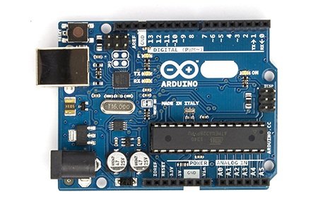
Arduino is an open source prototyping board which is made around ATmega328P; it has 14 GPIO (general purpose input output) pins, out of which 6 pins has capability to do analogue functions, all the 14 pins has the capability to digital functions.
A USB 2.0 type B placed right corner of arduino (depending on how you place) for powering and burn programs to microcontroller. A reset switch is placed left upper corner of arduino board for restarting the program within the arduino itself.
The Arduino board has built in programmer which burns the program to ATmega328P microcontroller via USB. A separate DC jack is provided for powering the arduino from external voltage source ranging from 7V to 12V (has built in voltage regulator).
Some specifications of arduino:
- Operating Voltage: 5V on USB and 7-12V on DC jack.
- Digital I/O pins: 14 (6 of which can do PWM operations)
- Analogue input pins: 6
- Flash memory for storing program: 32KB
- RAM: 2KB
- EEPROM: 1KB
- Clock Speed: 16MHz
- DC output current per I/O pin: 20mA
Note: The above specification is only applicable for ATmega328P based arduino microcontroller.
How to make one on a breadboard:
If the prototype of your project is complete and you want make it permanent on your project box? Actually you no need to place the whole bulky arduino board into your project box.
ATmega328P with few external components is enough to execute the program and control the peripherals that you connected with the microcontroller.
The arduino board is used to burn the program to microcontroller and provide some protection against the glitches that we make during prototyping.
DIAGRAM:
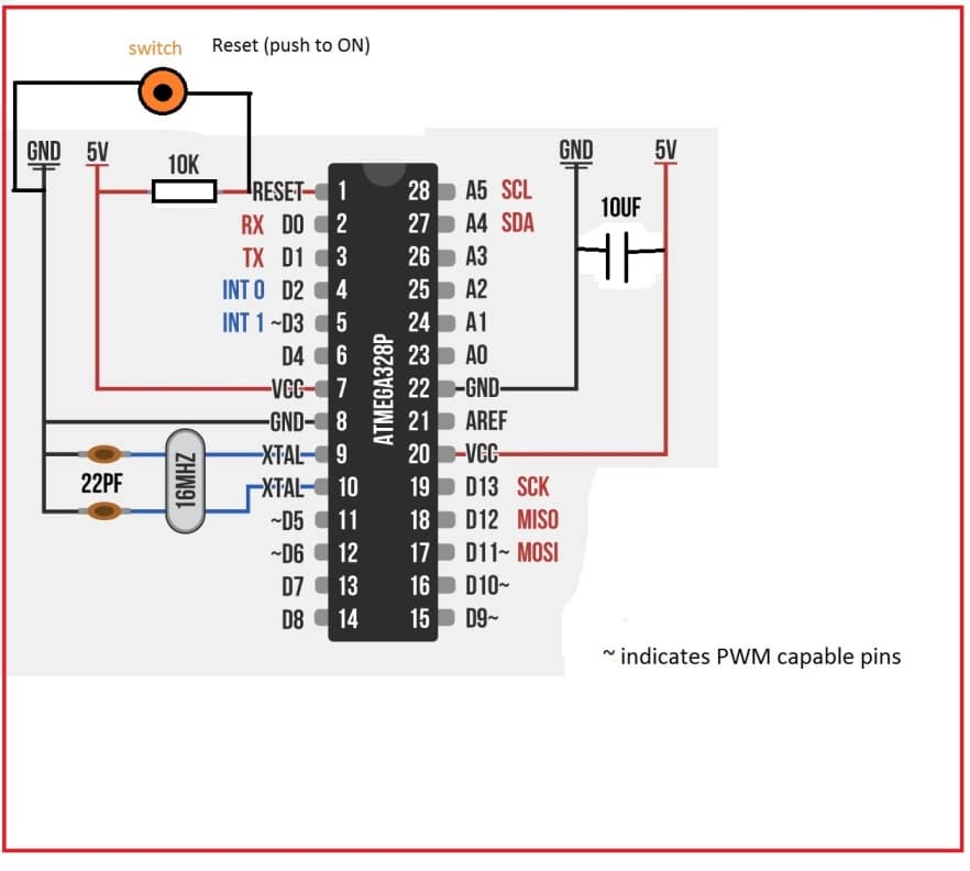
Once the project is complete you may pluck out ATmega328P and connect few external components as shown in diagram and you may solder it to PCB to make it permanent.
For your next project you no need to buy new arduino board, instead you may purchase the ATmega328P and few other external, which cost effective and make your project more compact.
How to Program ATmega328P when it is on breadboard:
Method 1:
The easiest and laziest way program the ATmega328P is with arduino board itself. Insert the ATmega328P, burn you program and pluck it out, insert it on your project.
This method is adaptable when your project has 28 pin IC holder (so that ATmega328P can be removed easily) and the ATmega328P is easily accessible.
Here is how to do it:
Download Arduino IDE form arduino’s official website and install on your computer.
Update the driver for the arduino board on your computer (no need to do, if you are using Linux based computer).
Insert ATmega328P on arduino board in right direction and make sure it has bootloader.
Select “Tools” > “Board”> “Arduino/Genuino UNO”
Plug the arduino to your PC and select right port for your arduino (vary computer to computer. Select “Tools”> “port”).
Compile the program and click the upload button.
Remove ATmega328P and insert it on your project.
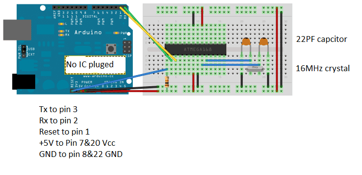
Method 2:
If you re-program the microcontroller frequently and hardware of your project is inaccessible, then this method is best for your project, especially when ATmega328P is soldered directly on PCB.
NOTE: Make sure the power supply from external circuit is disconnected before proceeding; we are going to power ATmega328P from arduino board.
Diagram:
Select “Tools” > “Board”> “Arduino/Genuino UNO”
Plug the arduino to your PC and select right port for your arduino (vary computer to computer. Select “Tools”> “port”).
Compile the program and click the upload button.
Comments
sir is there any time dealy relay mean to say that
lets say a sytem gives signal to that time delay relay than that start a timer and than give a output signal to operate a small 5 v relay after ,settled time ie. ex after 1 hour or 45min.
the link which you sent using iC 555 can also be used….
Hi Gurmel, for the first timer you can use the following circuit
https://www.homemade-circuits.com/2013/02/make-this-simple-delay-on-circuit.html
then attach the relay to switch ON the next timer which can be an timer circuit such as a 4060 timer
sir can i didn't understand about these thing buffer etc . can u plz share step viz circuit for it like 1ohm resitoor to base of that particular transitior and all that .
plz provide components details i will really appreciate.
led are those which are commenly used in inverters for various indications.
I think using an opto coupler will be a better idea than a transistor.
you can employ the first circuit from this article:
https://www.homemade-circuits.com/2013/02/how-to-drive-relay-through-opto-coupler.html
remove the relay and use the collector for feeding the Arduino, replace the 12V supply with 5V.
the opto LED with a 10K resistor can be then connected with the external blinking LED
You are doing a nice job sir. please what changes can be made on the setup to be able to run Arduino nano programs on the bread board set up above. I know they use the same microcontroller but the atmega 328 in nano seems to have up to 32pins instead of 28. 16Mhz crystal oscillator is connected between pins 7and 8 in nano while the schematic above shows 16MHz oscillator at pins 9 and 10.
Thank you Moses, As we know Nano is a PCB Board, loaded with Extra Stuff:
Arduino Nano looks like it has “more pins” because of extra power pins, USB to serial chip, voltage regulators, etc.
But actually the main chip inside is still ATmega328P which has only 28 pins.
The Nano’s pin numbers (like D13, A0, A5, etc.) are just labels for the same physical ATmega328P pins, arranged nicely on headers.
XTAL Pins Are the Same Internally:
The ATmega328P always uses pin 9 (XTAL1) and pin 10 (XTAL2) for the 16MHz crystal.
The Nano board just routes those internal chip pins to external PCB tracks which may make it look like they are on pins 7 and 8 because of PCB layout, not because of any actual change in chip pinout.
sir i have a circuit which has a led and ita blink at for on and off for 500ms continue .
i want to tap that that on off signal from led terminal and feed it to Arduino .
does doing this can affect to performance of circuit or to led on off performance??
Hi Gurmel, you can extract the frequency from the LED, it will have no impact on the LED operation, but make sure to use a transistor buffer in the middle having a high resistor with the base, this resistor can connected with the LED for the extraction.
Hi vijay,
No, you can't. The above article is only dedicated for ATmega328P. If you do the same for Atmega32 you will end up in errors. Use appropriate programmer to upload the code for ATmega32. You can use Arduino UNO board to program ATmega8 and ATmega16 and some other microcontrollers, not with the above schematic, but you can find schematic around the internet.
Best Regards.
Sir can I able to burn 40 pin with the same circuit by using breadboard with arduino uno
Thanks for your reply sir. My question is by using arduino uno we can able to program the atmega328 which is a 28 pin microcontroller. As per your above tutorial configuration can I able to upload the program in 40 pin atmega32 by using arduino uno. I hope you may understand my question now.
Hi Vijay,
Can you please elaborate your question.
Vijay, I am not sure about it, Mr. GR will be able to answer this, hopefully soon.
sir,can i used capacitor C1-10,000uf and 63v istead of 25v and also what am i used instead of choke 2mh its not available in market easily can imake its on bolt to do more turns on it.
zahid, no that will not do, you must go exactly as recommended in the article.
please comment under the relevant article
sir, please tell me in induction heatar i used a single 2uf and 400v capacitor tank instead of 6 330nf and also make a choke 2mh on iron core of 20 turn beacuse lack of avaibility in market but circuit not operate then what iam do.
zahid, which circuit are you referring to?