In this article I have explained a VLF receiver circuit used for detecting insect wing beat signals, the idea was investigated and built by Mr. Steven Chiverton.
Insect Wing Triggered ELF
An incredibly fascinating electrical outcome successfully identified with the VLF are wing sounds triggered when bugs like bees, flies, and mosquitoes fly within a few feet of the VLF whip antenna.
The ensuing signal is a buzzing noise nearly the same as what may be listened to by ear, in spite of this, this impact is brought on by electrostatic releases every time the insect's wings flap.
It can be considered that electrostatic charges (static electricity) are amassed on the insect's wings then simply thrown out through each wing whip, producing a "modulated" electrical field around the pest at the identical frequency as the wings whisk.
Big insects, along the lines of wasps, Yellow jackets, Bumblebees and honeybees, render notably powerful buzzing sounds in the headphones-easily heard once those insect fly within 4 feet (1 meter) of the VLF antenna.
Mosquito Wing Beats
High-pitched Mosquito wing beat noises is generally noticed the smaller bugs within a couple of inches of the VLF Receiver's whip antenna.
Particular types of flies as well as other pesky insects possess considerably more electrostatic "buzz" out of them compared to other forms - Bees and Horse Flies, in our findings, include the loudest "buzz" in the earphones!
This might likewise have something connected with the structure of the insect's wing, with specific form of bug wings higher susceptible to static electricity build up and ensuing discharge.
There could be insect physical electrical releases produced within the insect's wing muscle tissues that help cause this , although not much is recognized concerning this occurrence.
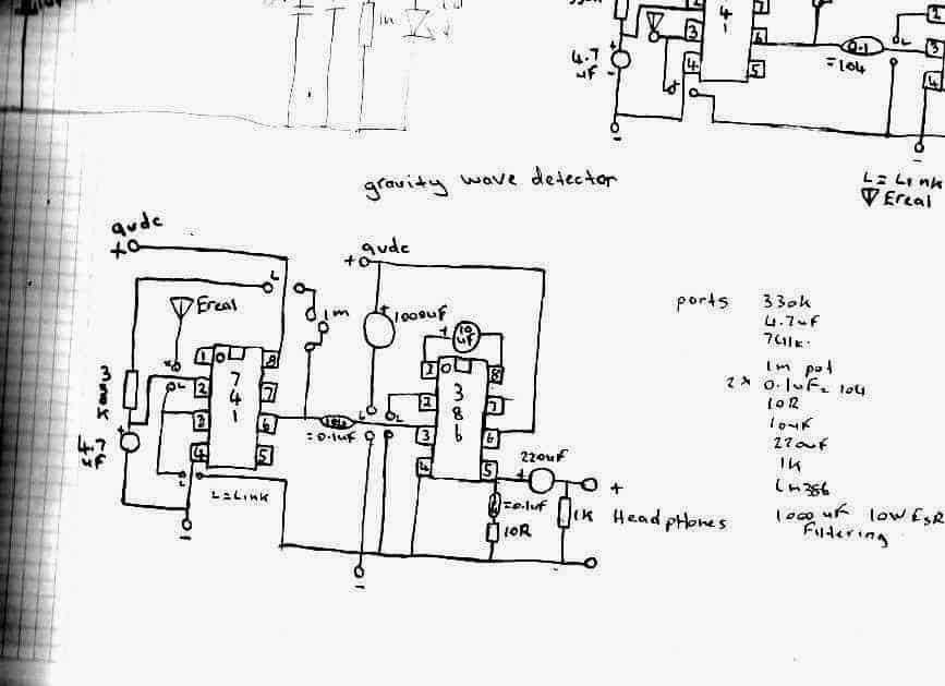
I've listened to sound recordings like whistlers etc and not one of these sounds matches the recordings I've collected from what I've received on my gravity wave detectors,
Detecting UFO Sounds
I'm working on 2 new VLF receiver circuits to receive these mystery VLF signals whether they be UFOs , there’s no info on these signals and there relation to UFOs if there’s one,
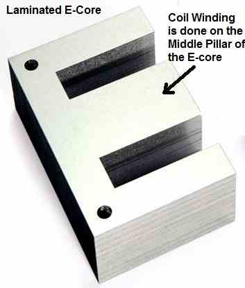
But I recall stories of people who hear low humming noises coming from UFOs , it’s a very low frequency signal itself and maybe if it uses ac it also covers, the VLF band of frequencies to, anyhow the iron peaces I need to make the core to concentrate the electromagnetic flux has been discontinued at dick smith electronics even though its in there catalog.
But I have enough in my collection to make one flux concentrator for the sensor coil
That fits the closest to the inside circumference of the plastic spool the coil is around.
I'll try jay car electronics to see if they have the same sizes I need for the next planed VLF sensor circuit,
Without the core to concentrate the electromagnetic flux, the signal reception is week but when you put a peace of the core into the centre of the coil the sensitivity jumps more and even more when you sit another core peace on top of the first one
These core peaces can be covered in heat shrink tubing to make it all hold together to form a single looking long core.
I have a number of the pieces so far but they are barrel shaped , so ill have to build the core with all these peaces , and hopefully jay car will have them to so I can construct the second core , for the other circuit to .
If you have read the top bit I to have received buzzing noises from fly’s but with one of my most sensitive gravity wave detectors and it has no areal just a sensor capacitor.
My latest VLF receiver tests have changed when I solder new 9 volts battery snaps into it now it was then more sensitive to the ac mains and recently I made a new lid for the VLF receiver circuit and had to resolder the wires to new leds I put into it now the circuit appears to be less sensitive to the ac hum as its lower as if the circuit is filtering it down or attenuating itself, but it still picks up the ticks from my watch at a good distance.
Using Zero Point Energy
I brought a few DVDs on ebay one called Tesla hunt for zero point energy and the other about Nazi flying saucers how they work something you cant get here so ebay was the place to order them on,
I've brought a number of emf detectors before to, off e bay but one seems to be really good but have got no ufos or ghosts with it and its sensitive but no ghost then to test it on but the one that's the k2 emf detector registers near the fridge here but nothing else that is ac powered gives a reading as if the ghost I saw last night likes to hide inside the fridge hehehehe
Anyhow, I've recently built a new insect gravity wave detector I copied it from my first old design which to my surprise senses insect wing signals from only stripped bodied flies which there isn't any here so far as the whether isn't to good
When I took my old design out and built a neon from it I discovered why it worked so well I mistakenly used pin 8 as the positive input and not pin 7 so I discussed it with Dave dede and he built it and got some bizarre results to and even more as pin 8 is not used on the 741
But Dave found a circuit on the Internet a Chinese one and in the circuit drawing they also used pin 8 for reasons we don't know cant speak Chinese heheh but a little looking around I find pin 8 also has another purpose
I forgot what it is but listed as something else other than just nc so anyhow I fired up my new circuit and even though the only 2 flies that flew by didn't have stripes on them and were to far away to register
Detecting Remote AC Hum
I noticed that the extra sensitivity is very interesting what are they really hiding and why is pin 8 doing things unheard of or not said so I sat outside with the detector on top of an outdoor table and I noticed that when I run my finger on the wooden part of the table the wooden slats that make the top of it I can hear it through my headphones strange
Even more bizarre is the unusual sensitivity to ac fields I bring the detector inside and with my bare feet on the ground
I can hear the ac mains hum but it goes away when I lift my feet off the ground as if the underground power here is absorbed into my body and re radiated so the detector can hear it again now I still have my old insect gravity wave detector design here
I'm using on it and the new one, 2x 9 volts batteries and they are due to be replaced as these nmh rechargeable may have had there days as one keeps loosing power.


Comments
Dear Sir Swagatam
I am here again very soon. By searching through internet, I was directed to my favorite site (Homemade-circuits.com), which I like it very much. In the attached link I saw three tested circuits which all are interesting to me.
Please let me know the CD4011 based circuit is suitable for running away cats, dogs and foxes and how far goes the output waves of it.
https://www.homemade-circuits.com/ultrasonic-pest-repellent-circuit/
Best regards
Emad
Thank you Emad, for your kind words, I appreciate it very much.
All the designs from this article were submitted by external authors and I have not yet confirmed their results practically.
However I strongly believe that the last IC 555 based circuit may be effective in driving away animals like dogs, cats and rats.
This is because the last circuit is a pulsed circuit meaning the ultrasonic waves will be emitted through intermittent pulses which can be quite disturbing for the animals.
That said, the frequency of the ultrasonic sound must be perfectly adjusted and optimized so that it is at the most disturbing range for the pest animals.
Dear Sir Swagatam
Hello. Please excuse me a lot that I had not referred to this page till now. Thank you very much for your good and useful information. would you please tell me
1. Is the picture of component that I will send to your Email address is the component that you name it as ultrasonic piezo. what are other names of this piece? I am confused.
2. should I use it or a piezo speaker in the last circuit ( No 3)?
Best regards
Emad
Hi Emad,
Are you referring to the following circuit?
https://www.homemade-circuits.com/wp-content/uploads/2022/03/pulsed-pest-repeller-circuit-1200×489.jpg
In this circuit you can use a simple piezo transducer or a tweeter. Tweeter will be better I think…
Dear Sir Swagatam
Thank you a lot for your response. yes! In addition to the link you referred me to, I also mean the following two links:
1. Title: Dog deterrent circuit: SPKR1
https://www.homemade-circuits.com/dog-barking-preventer-circuit/
2. Title: Ultrasonic transducer (transmitter)
My comment dated Nov 5 2023 in the following link
https://www.homemade-circuits.com/insect-wing-signal-detector-circuit/comment-page-1/?unapproved=146907&moderation-hash=9eb23e2f2055e8735e68f4d736d4b8a5#comment-146907
https://www.homemade-circuits.com/wp-content/uploads/2023/11/dog-repellent-circuit.jpg
Would be very glad and thankful to have your kind response.
Best regards
Emad
Thank you Emaad,
Yes, you can use any standard piezo transducer as the speaker in all those circuits, however a tweeter speaker would also work in these circuit. Any one of the following will do:
https://www.homemade-circuits.com/wp-content/uploads/2020/02/piezo-transducer.jpg
https://www.homemade-circuits.com/wp-content/uploads/2021/02/Tweeter-compressed.jpg
Dear Sir Swagatam
Thank you very much for your valuable and very useful information. God bless you.
Best regards
Emad
You are most welcome Dear Emad.
Dear Sir engineer Swagatam
Please excuse me for leaving a message here. Could you kindly tell me what words should I search on your site full of very interesting circuits so that I can get a circuit that will repel animals such as dogs, foxes, etc away my garden? and can stay on all 24 hours and for days?
Thank you in advance for your kind reply
All the best to you
Regards
Emad
Thank you Emad,
You can try implementing the last circuit from the following post to repel dogs and foxes. In order to make it work for 24 hours and for days you may have to use a solar panel and battery to power the circuit.
https://www.homemade-circuits.com/dog-barking-preventer-circuit/
Dear Sir engineer Swagatam
Hello. I did not expect to receive your kind response so soon. Thank you very much Sir. Is the circuit you referred me to under the title “Dog Deterrent Circuit” is suitable for cats too? and does this circuit repels animals which are away 30 meters from the circuit? Thank you again and God bless you
Best regards
Emad
Dear Emad,
Sorry, I mistakenly said that this circuit would repel dogs and foxes, actually it won’t.
It can only discourage the dogs from barking.
Unfortunately there cannot be such a circuit that can repel dogs and cats, according to me.
Dear Sir Swagatam
Hello. Hope you are fine.
I sent a circuit through your Email address just now.
I would be glad if you take a look at it which seems interesting.
Best regards
Emad
Thank you so much Dear Emad,
However, I checked all my three emails but I could not find any emails from you.
Could you please tell me on which email ID did you send the message, or if possible could you please send it again?
Dear Sir Swagatam
I sent it again just a few minutes ago to your Email: hitman2008@gmail.com
Best regards
Emad
Thank you so much Emad,
I got it now!
The design looks very nice, since it will deliver a powerful push-pull ultrasonic wave output enough to cause a lot of irritation to animals like dogs and pests.
https://www.homemade-circuits.com/wp-content/uploads/2023/11/dog-repellent-circuit.jpg
Dear Sir Swagatam
I disconnected pin4 of ICs and connected them to -9; I also mounted two new ICs instead of burnt one’s still, there was no output in the loudspeaker.
All the best to you
Emad
Dear Sir Swagatam
It is great Sir and I appreciate your kind response. I will share the results when it is done. Thank you very much.
By the way, the reply button was absent below your resent response.
All the best to you
Truly yours
Emad
Thank you Dear Emad,
Sure, you can try the new circuit and let us know how it goes.
Yes, the reply button is missing, and I have no idea how to solve this problem at the moment, I will keep trying though.
All the best to you.
Dear Sir Swagatam
Thank you so very much for:
1. your response to a completely wrong circuit that was not yours and was not published on your site.
2. for your great favor in providing me with a circuit that you confirm have confirmed.
Now, could you please advise me on whether TIP32C and TIP31C are suitable substitutes for BD679 and BD 680?
All the best to you
Emad
Thank you Dear Emad,
However the new circuit is also not designed by me and is not tested practically by me, but looking at the configuration I can say it is correct, and should work.
Yes, TIP31, TIP32 can be used in h-bridge configuration.
Dear Emad,
Please read my previous comment reply, I have explained everything in it. I hope you are able to find it.
Pin#4 must go to +9V and not -9V.
Dear Sir Swagatam
I did this project today. Shortly after switching on the circuit, both ICs esp.IC2 became hot and eventually burnt out. Upon further inspection I discovered that pin4 of both ICs were receiving a voltage of +9 instead of -9. Am I right? Is this the only wrong issue in designing this circuit which seems to be good? I kindly request your expertise in reviewing the circuit to identify any other potential issues that may have contributed to this incident.
I can assure you that all components and wiring connections have been correctly implemented. Your kind attention to this matter would be greatly appreciated.
Best regards
Emad
https://www.homemade-circuits.com/wp-content/uploads/2023/11/dog-repellent-circuit.jpg
Dear Emad,
I am very sorry, that circuit seems to be completely wrong, because the pin#3 of both the ICs are shorted together. Pin#4 pins are connected correctly with the +9V terminal, that is correct.
I would request you to please ignore the previous circuit and try the following circuit instead, and see how it works::
https://www.homemade-circuits.com/wp-content/uploads/2024/03/IC-555-push-pull-oscillator-H-bridge-circuit.jpg
Dear Sir Swagatam
Hello. I implemented the circuit today after about a month of illness. please accept my apologize for being late. Soon after I connected the circuit to 9V the left BD680 became hot and I disconnected it from power supply. would you please take a look at the circuit and respond me weather all wirings are correct? I assure you of my assembling.
God bless you
With big thanks
sincerely yours
Emad
No Problem Dear Emad,
Glad you have recovered from the illness.
Please modify the circuit by adding resistors to the bases of all the 4 transistors, as shown below, and check if that helps or not:
https://www.homemade-circuits.com/wp-content/uploads/2024/04/555-motor-reverse-forward-circuit.jpg
Thank you dear Sir Swagatam for modifying the circuit. Would you please write the amounts of the resistors?
Best regards
Emad
You are welcome dear Swagatam and thank you so very much for publishing it which would hopefully be good for visitors of your site.
I will definitely implement it after providing the semiconductors and let you know the result.
All the best to you
Emad
No problem Dear Emad, hope it works for you. All the best to you.
No problem dear Swagatam
I promise that I will definitely let you know if I find a circuit that would be practical.
Thanks a lot for your kindness
Best regards
Emad
Thank you very much Emad,
I appreciate your kind feedback, all the best to you.
I’m interested in detecting woodpeckers damaging the exterior of my house. I think I could trigger a loud noise to keep them away if I could detect their pecking which is in the 50 – 80 Hz range. Would you use this circuit as is for this purpose or what modifications would you recommend.
I am not very sure whether or not the above circuit will be able to detect 50/80Hz sound and trigger an output horn. I guess your home exterior is made up of wood, in that case you can install a sound activated switch with the house wall so that it can detect the loud sound made by the woodpecker and switch ON an attached horn or siren.
More about the sound activated switch can be learned from the following post: You can build the first circuit and plug the MIC with your house wall for detecting the sound.:
https://www.homemade-circuits.com/simplest-sound-activated-relay-switch/
Hi Steven,
I found this page was linked to from
https://www.homemade-circuits.com/very-low-frequency-vlf-detector-circuit/
and the link was labelled as “gravity wave detector”.
In the text, you mention “these sounds matches the recordings I’ve collected from what I’ve received on my gravity wave detectors”.
This is a bit confusing, as it seems this isnt your gravity wave detector circuit page?
Also I noticed that the schematic image file name is “peziogravitywavedetectorcirciut-1.jpg”, which doesnt match the schematic, as the schematic doesnt use a piezo element. Can you please post a schematic of your gravity wave detector that I presume uses a piezo element?
thanks,
JEFF
Hi, I appreciate your efforts, thank you, I built your circuit (Insect Wing Signal Detector Circuit)
it did not work for me , the circuit is not clear, pls , send me a schema, thank you!