Are you feeling vulnerable or suspecting a possible LPG gas leakage in your house? Then may be this gas leakage alarm circuit might help you.
Written by: Sai Srinivas
The Concept
This circuit is a simple solution for detecting LPG gas leakage in households which causes severe physical and monetary losses if left unattended for a long time!
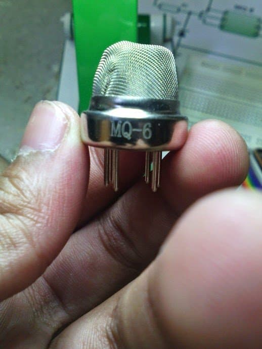
This circuit uses a MQ-6 gas sensor which is more sensitive to LPG gas than other sensors like MQ-2. The MQ-6 gas sensor consists of a small heater coil and some chemical composition of the compound SnO2(Tin Dioxide).
The heater coil remains heated always as long as the circuit is on and hence, the circuit continues to draw current even when there is no gas leakage.
Audio/Video Reperesentation
WORKING PRINCIPLE OF THE CIRCUIT:
First let us understand the pin outs of the sensor MQ-6. This sensor consists of six pins but in this circuit, two pairs of shorted pins are made by shorting two—two pins separately such that two pins together form one pair and another two pins form another pair and the other two left over pins are used normally without any shorting.
Here, we named one pair of shorted pins as XX and other pair as YY so that we could understand the circuit more easily.
Gas Sensor Pin Connections
The pins can be connected either way round, as they does not have polarity.
The heater pins are named as H each. While the pin XX is connected to Vcc, the pin YY is connected to the base of the transistor BC548. The heater pins can also be interchanged. The preset resistor is used to set the sensitivity.
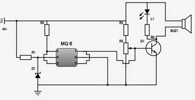
The gas leakage alarm circuit uses a BC548 transistor to turn on the buzzer whenever LPG gas is detected by the sensor.
Initially, when the circuit is turned on, the coil inside the sensor starts heating up and the current flow through the coil is controlled by a 33 ohms resistor while the zener diode makes sure that the voltage flow does not exceed 5.1V.
The XX pin is connected to the +ve of the power supply via a resistor while the YY pin is connected to the base of the transistor BC548. The 100K preset resistor is used to set the sensitivity.
When the gas concentration in the air increases, its output goes high and it makes the transistor to trigger the buzzer and a LED. The buzzer and the LED remain powered until the concentration in the air decreases below the specified level.
SETTING AND TESTING THE CIRCUIT:
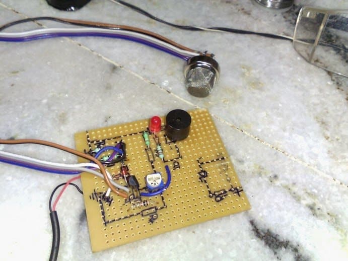
Use a general purpose PCB for assembling the circuit and use a ribbon cable to connect the MQ-6 sensor to the circuit. After completion of the making of circuit, take it near the LPG gas stove and switch on the power supply.
Make sure that there are no flames or electrical devices that could cause sparks in the vicinity of the stove and the circuit.
Now, turn on the gas stove without lighting it and adjust the preset using the screwdriver so that the buzzer rings only when there is reasonable gas concentration in air. After the adjustment is over, enclose the circuit in a suitable casing and install the sensor nearer to the gas stove.
Make sure not to include any electro-mechanical devices in the circuit as the sparks that might be produced while they are working could cause fire when there is a gas leakage.
PARTS LIST:
- R1 – 33 ohms,
- R2 – 2.2K,
- R3 – 100K preset resistor,
- R5 – 390K,
- R6 – 2.2K,
- D1 – 5.1V, 1W zener diode,
- L1 – Red LED,
- Q1 – BC548,
- BUZ1 – 6V buzzer
- Power supply – 6V, 800ma(should not exceed this voltage)
Prototype Image
DISCLAIMER:
While this gas leakage alarm circuit is tested for satisfactory working, it might fail sometimes to give a buzzer indication due to any reason like for example, power failure. So, please don’t depend entirely on this circuit and keep an eye on the stove always.
I am not responsible for any consequences that you might face while and after making this circuit.
Video Demonstration
The video demo for the same can be seen below:
Making an LPG Gas Sensor with MQ-135 Gas Sensor Module
MQ-135 is a gas sensor designed to sense or detect gaseous substance such as an LPG gas leakage and generate a corresponding positive output voltage.
In this post I have explained how to connect the pinouts of an MQ-135 module with a relay driver stage correctly.
The MQ-135 module is an enhanced or upgraded package of the basic MQ-6 gas sensor module. In this module the analogue output from the MQ-6 is converted into a digital output, with an adjustable sensitivity feature.

The conversion of the analogue to digital is done through a comparator IC, usually an LM393.
How The MQ-135 Module Works
As described above the MQ-135 works by converting the analogue signals from the sensor unit into digital output through a comparator.
The module basically features 4 pinouts.
- Vcc
- Ground
- Digital Out
- Analogue Out
Sensor side View

Component Side View

The analogue out is directly taken from the MQ-6 sensor pin.
The Vcc works with a +5V DC supply, ground is the negative or the 0V terminal of the module.
The digital output is derived from the output of a differential comparator using the IC LM393.
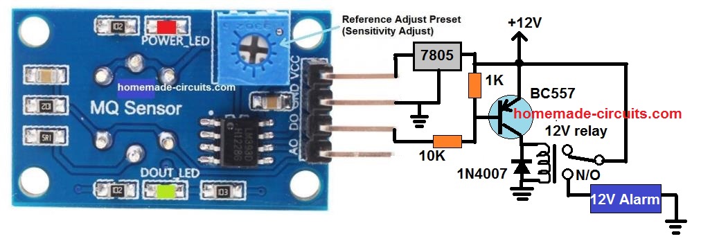
How to Connect a MQ-135 Gas Sensor with a Relay
Recently I purchased the MQ-135 module and while testing it I was surprised to see my external relay driver not responding at all. However, since the module's in-built LED was illuminating, I knew the module was OK.
I assumed and expected the output to produce a positive digital signal for every input detection. However, I simply couldn't get this working.
Then I realized that the IC LM393 has an open collector output, meaning its output pin was associated with an open collector of an internal NPN BJT.
And since my external relay driver NPN BJT was unresponsive meant that the module did not have a pull up resistor with the LM393 output.
I quickly configured a pull-up resistor with the comparator output pin and tried again. The relay now responded but with an opposite effect.
Meaning, now the relay remained switched ON when powered, and switched OFF as soon as the sensor detected gas. This was very undesirable, and was due a wrongly configured module.
It seemed the manufacturer missed the fact that the LM393 is not an op amp, and its input pins needs to be wired in a way opposite to an op amp input wiring.
In other words (+) input pin should have been wired with the reference preset and the (-) input with the sensor analogue input.
Anyway, since it was not possible to modify the module PCB and the ICs input configuration, I ultimately decided to change the NPN relay driver with a PNP transistor driver. And this solved the issue.
Wiring Diagram
Here's the complete wiring diagram of MQ-135 for all the new hobbyists, who may otherwise find it impossible to drive a relay using NPN transistor, for a positive detection.
Maybe, for the future productions this issue will be addressed by the manufacturer and corrected.
MQ Gas Sensor with Relay Module Circuit for Alarm or Load Control
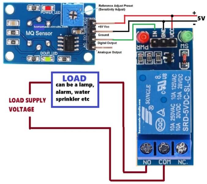
In this setup, we are using one MQ gas sensor module with one 5V readymade relay module, which then controls some load, like alarm or lamp or maybe sprinkler.
The MQ sensor gets 5V supply, VCC and Ground connected properly, so it keeps watching air all the time. Checking gas or smoke...air quality etc.
There is one small preset on the module which adjusts sensitivity. So we can decide when it should react, which level, since different places need different setting, so we turn it and fix point.
Now the important line is digital output pin that goes to relay module input. So whatever sensor decides, that signal goes straight there.
Relay module also runs on same 5V so no mismatch happens. Both stay happy with same level...
When there is no gas then sensor output stays inactive, so relay stays OFF, nothing moves, load remains OFF, all quiet.
When gas comes, then sensor changes state. So now signal goes to relay, and relay switches ON with immediate response.
As soon as relay gets energized, its contacts move. Now the COM terminal internally connects to NO terminal of the relay, circuit closes, so now load side gets power.
Then load starts, this could be alarm, light, or any safety device, depends what we connected there at the relay contacts terminals.
When gas goes away, then sensor goes back to normal, relay drops, contacts open, load turns OFF again, cycle complete.
So now we see, this is simple automatic system, just direct action. If atmospheric gas contaminates then circuit turns ON the load, if gas is gone then it turns OFF.
Also relay gives isolation, so load voltage can be different. It maybe higher or separate supply, but still safe, since control side and load side stay apart, which is useful in real use.


Questions & Answers
Does the MQ-135 module require warm-up? Can it detect gas leaks immediately upon power-up?
Yes MQ-135 module require warm-up, and it might not detect gas leaks accurately immediately upon power-up…
My detector is not working what is problem
See this article:
https://www.homemade-circuits.com/how-to-wire-a-mq-135-gas-sensor-module-correctly/
All the best things on the gas leakage alarm circuit, with a brief analyzed discussion and data on them. Such articles are not only knowledge enhancers but also very interesting to read and to learn to compare from.
Where to add a 12v small 400hom relay to power another AC device keeping the buzzer and LED?
connect it where the speaker is connected…but use 12V separately for the relay and make sure to add a 1N4007 diode in parallel to its coil