MOSFET based amplifiers as we all know are outstanding with their sound qualities and they can easily beat the performance of other counterparts based on power transistors or linear ICs.
Why use MOSFETs in Amplifiers
Amplifiers based on mosfets are not always easy to design or make.
Moreover after assembling a prototype, testing to perfection always remains an issue with new electronic hobbyists.
You might have come across many hi-fi complex mosfet amplifier designs, but might have not dared making it just because of the above reasons.
The simple mosfet amplifier circuit diagram is super simple to build and yet will provide you with a crystal clear 100 watts of raw music power that all the listeners will cherish for a long time.
The idea was developed a long time ago by the Hitachi researchers and still it remains one of the favorite designs of all time considering the involved simplicity against quality.
How the Amplifier is designed to Function
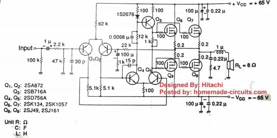
Looking at the figure we can understand the circuit with the following points:
- The involved simplicity would also certainly mean that some of the ideal features of the circuit was sacrificed in the design, for example it lacks a constant current source for the differential amplifier at the input stage of the amplifier.
- But this has no serious impact on the design, whatsoever..
- The differential amplifier makes sure that the input is sufficiently amplified to some reasonable levels suitable for feeding the next driver stage.
- The driver stage consists of a well balanced high voltage transistor stage which are necessarily positioned for driving the output power mosfets.
- The pot positioned in between the two sections of the driver stage is used for setting the quiescent current of the circuit.
- The output stage is a common push pull type of mosfet stage which finally provides the boost for amplifying the fed low signal music into a 100 watt thumping music over a 8 Ohm speaker.
- The shown parts might be obsolete today so may be replaced as follows:
- The differential transistor may be replaced with BC556.
- The driver transistors may be replaced with MJE350/MJE340.
- The mosfets may be replaced with 2SJ162/2SK1058
The below given diagram is the original design from Hitachi, see the preset arrangement for setting up the quiescent current. You must adjust this preset to set the quiescent current to zero before connecting the speaker.
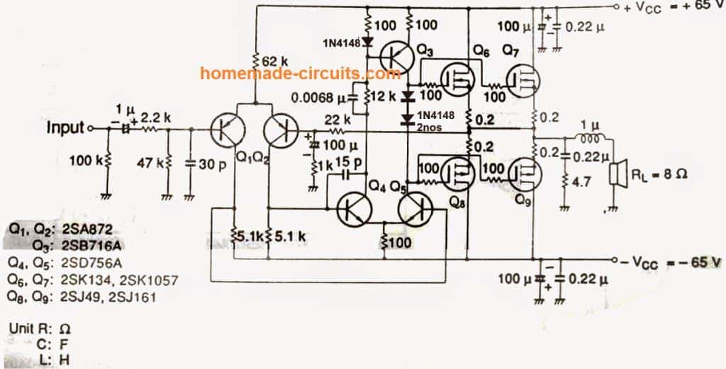
I have modified the above design by adding a couple of 1N4148 diodes in place of the preset. This gets rid of the preset adjustments and allows the user to directly switch ON the amp with a speaker connected.
Parts List
Resistors
All resistors are 1/4 watt, CFR 5%, unless otherwise stated.
- 100 Ohm = 7nos
- 100k = 1no
- 47k = 1no
- 5.1k = 2nos
- 62k = 1no
- 22k = 1no
- 2.2k = 1no
- 12k = 1no
- 1k = 1no
- 4.7 ohm = 1no
- 0.2 ohm / 5 watts = 4nos
Capacitors
All capacitors must be minimum 100V rated
- 1uF = 1no Electrolytic
- 100uF = 3nos Electrolytic
- 15pF = 1no Polyester
- 30pF = 1no Polyester
- 0.22uF = 3nos Polyester
- 0.0068uF = 1no Polyester
Semiconductors
- Q1, Q2 = BC546
- Q3 = MJE350
- Q4, Q5 = MJE340
- Q6, Q7 = 2SK1058
- Q8, Q9 = 2SJ162
- 1N4148 = 2nos
Misc
Inductor = 1uH, 20 turns of close wound 1mm super enameled copper wire, with 10mm diameter (air core)
Note: The resistor, and capacitor values are not critical, slight up and down will do, and will not cause any harm to the performance of the amplifier
Parts, PCB Images and Prototype
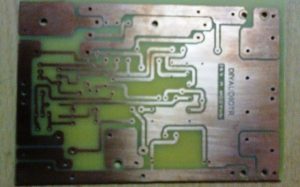
1) The first image shows the PCB which was used for the 100 watt mosfet amplifier circuit project
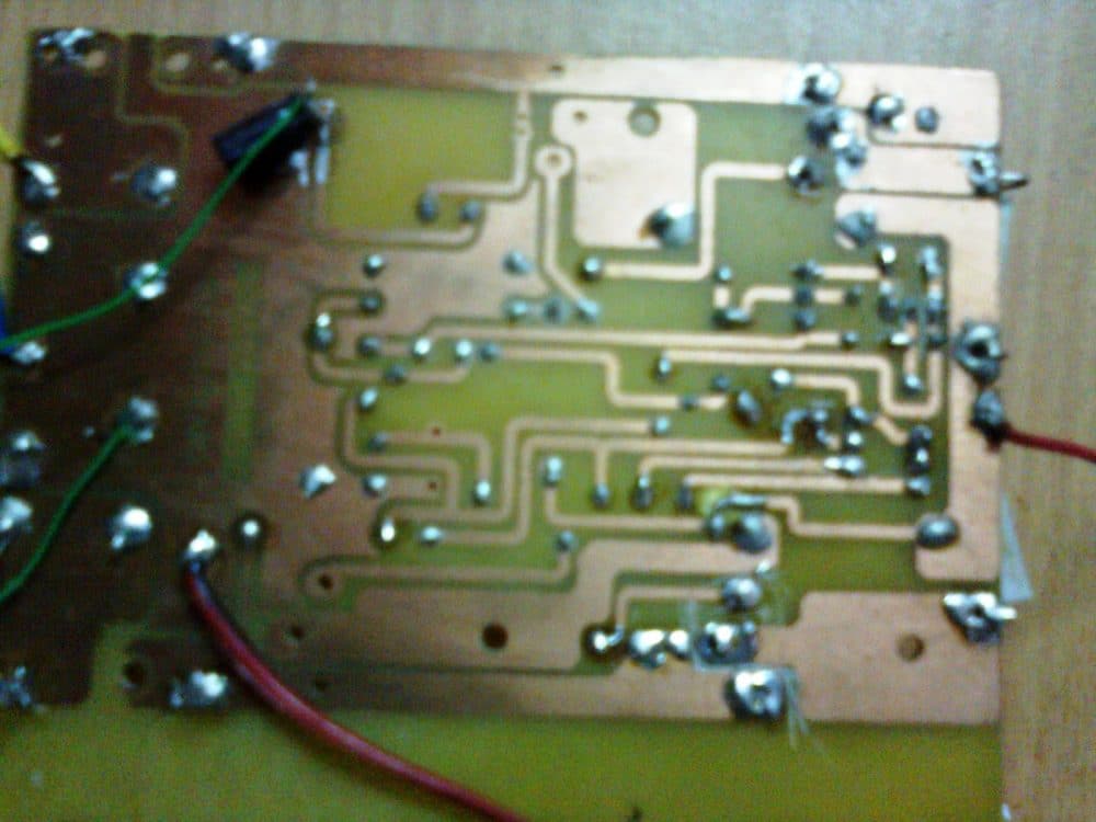
2) The second pic shows the soldered portion of the assembled circuit.
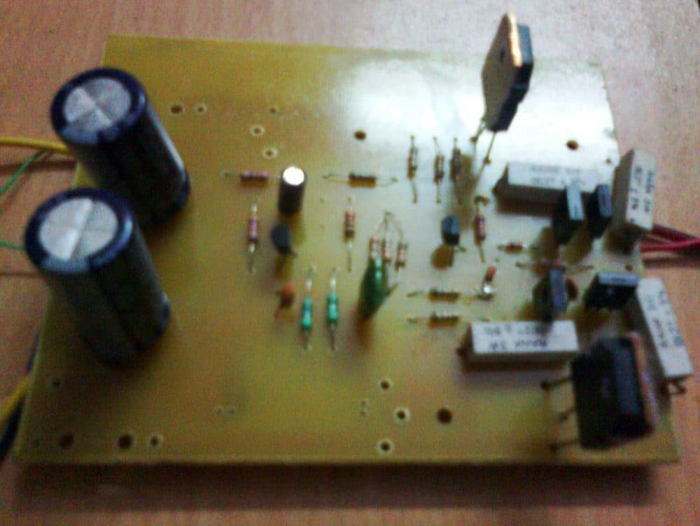
3) The third pic illustrates the components side of the assembled board
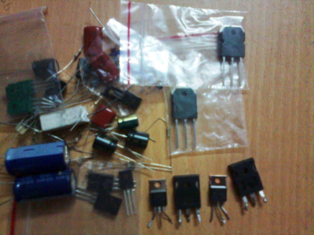
4) The fourth image relates with a few of the components involved with the the circuit making.
5) The fifth figure witnesses the speakers which was used for testing the amplifier with astonishing levels of clarity and superb power outputs :p
I used only a couple of mosfets which could generate power outputs well over 100 watts RMS, connecting more numbers in parallel can easily enable this circuit to cross beyond the 1000 watts mark.
If you are intending to buy a ready made power amplifier for your home, I would suggest, you build this one instead and be the proud owner of this outstanding home built power amplifier unit which would probably serve you for years.
The Design which I Built
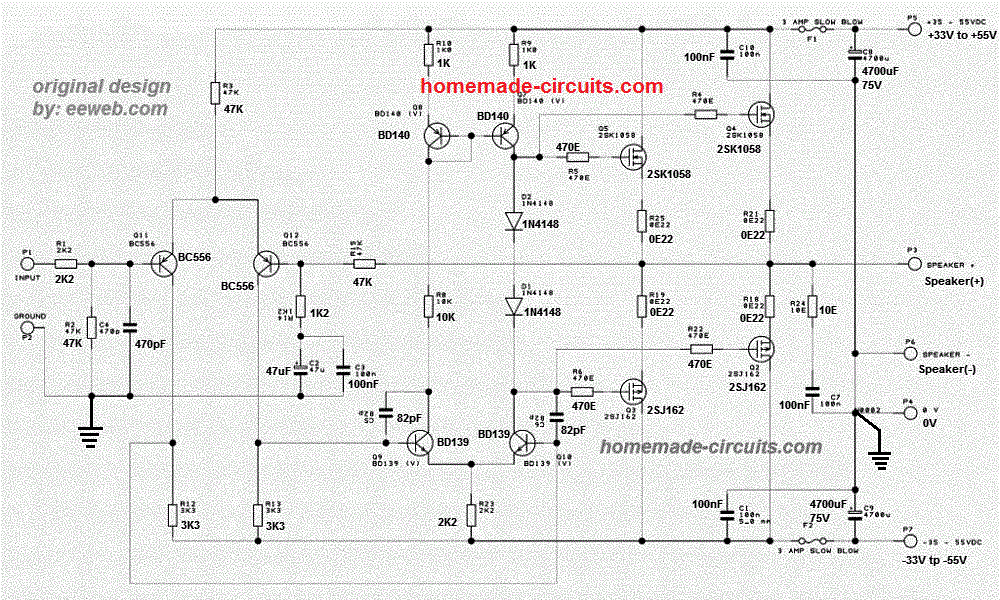
The circuit which I tested was taken from eeweb, and the diagram is shown below. It is similar to the above original design from Hitachi. However since this is the one which I have tested I would recommend you to go with this one.
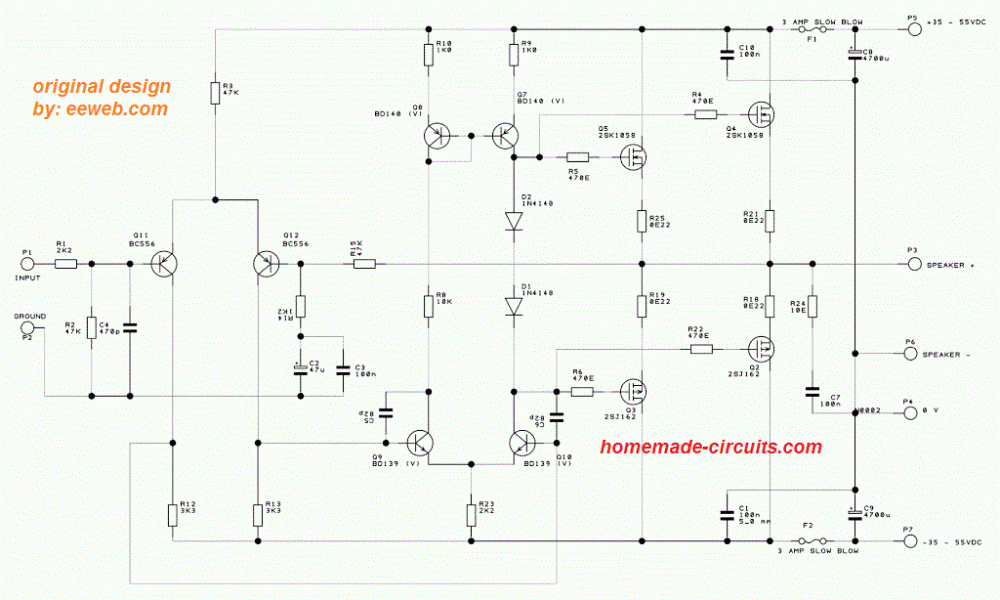
Circuit Diagram with Magnified Part Values
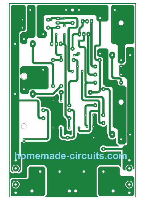
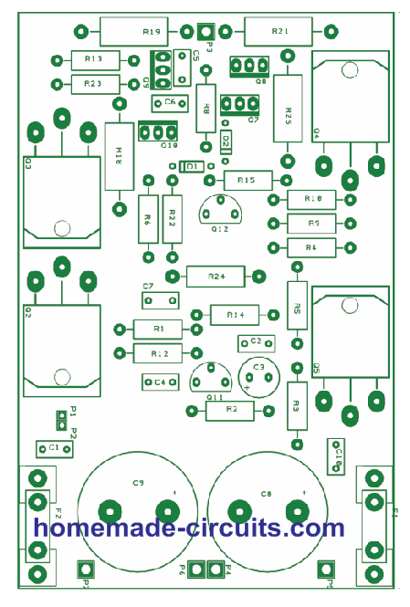
PCB Track, and Component Layout Diagrams
Credit to the Original Creator
PCB Dimensions are 120 mm x 78 mm



Questions & Answers
Hello,
first of all, thank you for the blog!
My question: could we run a +-100v psu directly on this pcb?
Hi, as per the voltage specifications of the transistors, a maximum of 60 V can be used. You can perhaps try replacing the BD transistors with MJE variants and then use 100V.
The first circuit is not working…am using 22vac secondaries, but am having constant voltage in my speaker stressing it and too much humming…
The first circuit was designed by Hitachi engineers, so it should work.
You can try the last circuit instead, it has been tested by me thoroughly. Make sure to use the PCB design for assembling.
Hallo Erstmal, wie wird bei dieser Platine der Kühlkörper montiert? Oder laufen die Mosfet ohne Kühlkörper?
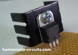
Hi, heatsinks are definitely required for the MOSFETs, you can put individual, standalone heatsinks for each of the MOSFETs, such as this one:
Hello dear,i need power suplly 12v to 55v for your circuit on car amp,can you help me?
Hi, you can try the first circuit from the following article. You will have adjust the zener value and the coil winding to get the required results correctly.
https://www.homemade-circuits.com/12v-car-laptop-charger-circuit-using/
There is no specifications on this project, what were the original Hitachi specs , if you know?
I would like to build it, can you supply/sell PCB?
Regaeds,
Tomo
The wattage specification will depend on the supply voltage used. Wattage = Supply voltage x 3 amp. Max voltage for the first two circuits should not be over 60 volts.
I would recommend building the last design since it is a tested one….and the wattage range can be as high as 300 watts.
Sorry…I don’t have the PCBs for this design.
please is the 2Sk1058 and 2SJ162 THE output Transistors ? and please if I replace the BD Transistors with Mje 340 and Mje 350; and I Replace the BC556 with 5401 . would it take up to 200v. because the transformer i have it’s a Center Tap transformer with a 100v-0-100v Ac output.looking forward to hearing from you . Thanks .
Yes those are 2Sk1058 and 2SJ162 MOSFETs.
Sorry, 200V would be too high…you can at the most use 120V DC, nothing above that….
And lastly. is there a way you can use only N-CHANNEL MOSFETS for the output stage.E.g IRFP260N
No sorry… the design should be exactly as given in the above article…
please can I replace the mosfets with these Mosfets.IRFP260N and IRFP9240? N-and-P Channel
If these are rated with 150V VDS then you can use them
ok Thanks . They actually Rated
200 VDS . BOTH.
IRFP260N and IRFP9240.
I really appreciate your kindness
Great, then it is absolutely fine, you can use them.
Hi Swagatam
I decided to install two fuses in my Trace Elliott GP7SM 130 power amp in the + & – power rails by cutting the traces and soldering wires to chassis mounted glass mini fuse carriers so as to make the measuring of the currant draw easier but I am confused as to how to properly set the quiescent current for this amp that uses 1 x 2SK135 & 1 x 2SJ50 lateral MOSFET’s.
The supply voltage to the main power amp with no pre-amp input connected reads: 143 Volts & 75 Volts + or – either side of chassis/ground.
I took a reading across the speaker terminal output with no load which reads: Approx. 35-mA, although that voltage reading does jump up and down a few mV’s while testing.
I read somewhere that to adjust the quiescent current correctly I have to short the input to chassis /ground so there is no signal entering the amp, insert a 4 Ohm load resistor (4 Ohms is the correct load for this amp) then set the multi-meter to 10 Amps on the positive rail and adjust the pre-set pot until no currant is drawn, however I have also read that the Mosfets on this amp should be set to be drawing about 100mA’s??? Help! I am confused!
Am I mixing up quiescent load with bias load and the need to insert a load resistance?
I have asked Trace Elliot if they sell an actual service manual that explains the correct procedure to set this amp up properly but they have ignored my requests.
Any help Swagatam would be much appreciated.
Kind regards “Confused”
Stefan
Hi Stefan, my idea of setting quiescent current is by connecting small flashlight bulbs in series with the positive/negative supply rails, and then adjusting the preset until the glow on the bulbs just disappear.
Yes you much short the input terminal with the ground, while doing the above setting up process.
Thank you Swagatam
I saw that somewhere on the web but couldn’t find it again and needed to know what size tungsten lamps to use.
I have heard they should be 1.2 watt 24 volt dc types!?
Are 3 volt flashlight lamps OK? Also do I have to have a load connected to the speaker terminals i.e. 4 ohms as the amp is designed to use, I only have an 8 ohm power resistor at the moment but could order a 4 ohm?
Regards
Stefan
Hi Stefan,
In my design I had used low current incandescent bulb which are normally used in 220V mains string lights. They are tiny around a cm long. Ideally the voltage of the bulb should be equal to the supply voltage of the amplifier, however practically a 24V bulb will also work nicely. The current spec of the bulb must be low, at around 100 mA.
3V flashlight bulb might not work according to me, they might burn at supply volts over 12V
Yes 8 ohm speaker load will do temporarily.
Thank you Swagatam
Much appreciated advice
Kind regards
Stefan
You are welcome Stefan.
Hi
I am looking to build this design, on the originals there’s an inductor before the speaker but on the tested designs there isn’t, what’s the reason for this and can I add one ?
Hi, The first two designs and the last design are not the same. The coil is used in the first two designs, it is not required for the last design which I built and tested.
Hi
Thanks for the reply. I will build up this circuit and test
What’s the power requirements per rail, will 3A be suitable?
No problem, please go ahead.
3 amps at 35 V, or 50 V will be fine for this amplifier
Hi Swagatam
This Hitachi circuit was and is obviously a very popular circuit and used in many Hi-Fi amps, in the 90’s the same circuit was used in a Trace Elliott GP7 SM bass amp combo, I have just part repaired a very badly bodged one for a friend and was stuck on how to set the quiescent currant correctly.
The Trace Elliott amp PCB board doesn’t really make it easy to temporarily install a couple of 100mA lamps to test the quiescent current temporarily so I was very interested in your diode modification but I was little disappointed that you didn’t include an explanation as to how this modification works and for the better but also if it would work in all types of amps including a Trace Elliott bass amp, also, I wonder why this diode method wasn’t used in the original design as surely two diodes are cheaper than a pot!
As you can imagine, this circuit would be driven very hard in a bass amp combo so I was worried that your diode modification may not be the best way to go.
Sorry if the above post appears to sound negative, it’s not my intention to offend.
Anyway your/this article is a great help even if I eventually go with the lamp method… Thank you!
P.S. While searching for pdf schematics and details of the GP7 I discovered a guy called mimi2008 who did a redesign of the original Trace Elliot GP7 PCB board, he moved a few components including the cooling fan supply arrangements.
I am looking at changing the cooling fan supply to either a 12 volt regulated “Heat dissipation” or a “PWM Controller” albeit only if the switching MOFET doesn’t induce noise into the amp although I guess that can be addressed with a cap or two as I find the original 270-Ohm voltage dropper resistor feeding the fan to be a bit Neanderthal for these times.
Unfortunately I can’t remember which site it was on but I have a pdf file of the board and circuit if anyone wants a copy.
Sorry for the war and piece post.
Kind regards
Thank you Stefan, for the detailed information! The two diode idea is not mine rather taken from the last circuit from the above article. I have not provided the explanation since I am myself not sure how the two diode idea helps to eliminate the preset. If I happen to figure it out I will surely update it here for you! If you are finding the resistor voltage dropper a bit Neanderthal, you can very well try using a buck converter instead, that would be a very efficient approach.
Good morning Swagatam ,
Is there any other ways to adjust the preset without the `rice bulbs`? I Cant find any rice bulns,so this option is a non starter for me.
Thank you .
Ernesto, the quiescent current adjustment is recommended only for the first design, not for the last design. Using small low current bulbs in series with the supply lines is the best method to adjust the quiescent current for amplifiers. You can try any small bulb, rated at around 100 mA current.
Hello, Sir,
Hope you are safe.
I have made the amp based on the last diagram,and am having some challenges as below.
with parts – BC640 , MJEs and 2 *4148
1.There is voltage at input pins of Mosfets thru the 470ohms resistors.
PSU 18 0 18 and on d1 & d2 there is 17.4 volts ,Thus a drop in approx 2v.
2.There is voltage also on the output(speaker out terminal) this drops to zero when i connect a speaker.
3.mosfets irpf450 and 9240 pair, there are failing a minute after i power up , they are heating up excessively .
4.Without the mosfets, there is a good audio buzz sound if i touch the input pin on the amp -with a small 5w speaker.
Kindly advise me on corrections.
Thank you in advance for your time and efforts.
Hello Ernesto, as far as my experience goes, the last design is a plug-and-play kind of design, in which nothing can go wrong. When I built and tested it, it started working superbly without any initial adjustments. I was amazed with its crystal clear sound output and flawless amplification.
Did you build it over the recommended PCB? Any other option might lead to errors and complications.
I think you should initially try the exact same MOSFETs as suggested in the article, just to be sure that everything is as per the diagram.
Hello Swagatam,
Thanks for your response,
Other wise I have to re-do my work.
Confirm we should not be getting any dc on the speaker output terminal?
Thank you.
You are welcome Ernesto, yes there should be no continuous DC across the speaker terminals.
Thank you sir for the link I appreciate sir
You are welcome Muhammad!
Thank you sir for the quick response.
As I have understood, amplifier is composed of three main stagess.the preamplifier stage,the driver stage and the final out driver stage am I right sir? If I know the current and voltage specs of every stage I think I will be able to build my own amplifier from scratch,I will be glad if u could tell me or refer me to a link that explains in detail all these parameters. Thank you once again sir.keep up the good work.
No problem Muhammad, I have a related post which you can refer to, it might help you to get some useful info regarding amplifier designing.
How to Design MOSFET Power Amplifier Circuits – Parameters Explained
Hi sir, God reward abundatly for the great job u have been doing. Regarding this amplifier I have a question. The above modified circuit been a mosfets amplifier,the voltage across the two diodes will be 1.4v right? If so,
1. is this voltage enough to drive the mosfets into saturation? Since mosfets require voltage not less than 2.5v base voltage to saturate.why I ask is because I once tried replacing mosfets with BJTs in a similar design an I got a cracking sound at low volume but with high volume,the sound becomes clear.this does not happen with the BJTs connected,so I totally may be the voltage across the two diodes in series wasn’t sufficient to drive the mosfets at lower volume pls is my assumption true?
2 I have seen many amplifier circuits having this kind of design (with two diodes in series )using BJT as output transistors, does that mean that this amplifier will work even when the mosfets are replaced with BJTs?
Pls sir I anticipate your response thank you sir
Thank you Muhammad, You maybe correct, BJTs require only 0.7 V to switch ON, while MOSFETs require much higher than this, however, in my prototype the amplifier perfectly well even at lower volumes, so I don’t think the two diodes are creating any problems.
You can try replacing the mosfets BJTs, just make sure to replace the base 100 ohms with higher ohm resistors
Hi, swagatam really nice and encouraging article. Now what exactly is the PCB design software did you use to design the board layout? Please am finding it hard to turn your images to a pcb.
Thank you Jeff, you will have to first change the colored PCB image into a back and white image then take it to a professional photo studio shop and get it converted into a positive film, then you can take that film to a PCB designer for generating real PCB samples.
First thank you for your time to make this blog active and available for us and by answering questions.I did this sir, however, after making the pcb I cant figure out the value of the components according to your prototype of copper layout. for example how can I know the value of R12 or R4 according to your components layout photo? even though you provided component values for schematic it is clear your pcb layout could not be the same as the schematic in terms of component position. kindly guide me further by providing the values of the resistors as per component layout. Thank you.
Thank you Jeff, The R12 and R4 and similarly all the other parts can be identified from the last diagram which shows the component layout of the PCB. The PCB layout is exactly as per the circuit diagram, and the components perfectly match with each other. Please compare them carefully, identifying the components shouldn’t be difficult.
Sir, I am planning to build this amplifier. But I was unable to find the mosfets any where. I am from Bangalore.
Can you please recommend me a dealer from whom I can purchase these mosfets?
Ganesh
Ganesh, the K1058, and J162 MOSFETs are available in most electronic spare retailers, and are the recommended devices for this amplifier. I think you should try getting it through some online sources, if you are not getting it locally.
Hi Sawgatham ,
thanks for guiding me on the sub woofer amp , can this circuit be made to go up to 200 W ,what would the power supply and also what about the relay protection , my area huge voltage fluctuations.
Hi Debu, yes, you can extend the rating of the amplifier to 300 amps by using 80 V to 100 V DC as the supply input at 3 amps.
for the speaker protection, you cn employ the following concepts:
https://www.homemade-circuits.com/make-this-amplifier-shortoverload/
will buz901-buz906 transistors work, that’s all I have to work with
sir
can you provided 6 n0s 2n3055 2nos bd139 02 bd140 ic lm324 audio amplifier circuits power suplay 12 0 12 volt
Ovinder, I do not have an LM324 based amplifier with me at this moment, if possible will try to find one and update it here….
Hi,
I am trying to build this amplifier. I can’t find the Mosfets you have prescribed at the power stage locally. I am wondering if 24N60CFD and its compliment can work as replacements. I am also looking for a circuit that can convert signal from a digital medium like USB flash to provide analog input to the amplifier.
Hi, SK1058, and J162 are very popular and easy to get MOSFETs, but if you cannot get them you can try any other near equivalent, having a VDS over 100 V, and ID over 25 amps
Please send me a clear diagram of your mosfet amplify with well specified resistors.. Is it possible for me to replace BD139 and 140 with TIP40 and TIP42 respectively?
The following is quite clear:
Check the collector/emitter voltage of the transistor from their datasheets and compare them with BD139/BD140, if they are almost similar then you can use them.
How much cooling are needed for BD139-BD140
Hi Swagatam, i would like to built the circuit which you had tested as per described. I plan to use power supply with 10 AMP, DC output approaching 85v 0 85v after the complete rectifier diagram with 22000uf capacitors, may I know is the small transistors (BC556, BD139 & BD140) need to be replace with higher value? If yes, what is the replacement transistor you suggested? Looking forward to hear from you soon, thank you in advance for your kind help.
Hi Jeffry, for the BD transistors you can use MJE340, MJE350, for the BC556, you can try BC640
Mpsa92 and 300v types and will be suited in the long tail pair.. electronics tech here and have built many mos and bipolar type amps for colleges over the years.
Their are a few mods that can be enfused with this circuit, such as better long tail design to stop that nasty thud at power on /off with speaker cone pop. A trim pot can also be added in the tail pair to zero off the output dc offset.
Even adding v limiting incase the fets take a nasty short to the outputs.
Yes, fets and more robust than bipolar transistors but, also more costly now.
I normally add speaker protection unit with say 4 second delay.
Happy building out there folks.
Wayne.
Thank you very much for your valuable feedback!
Hi Swagatam, thank you for your sharing. Just would like to confirm further, i just need to change the transistors to higher voltage and other components use for transistor can remain the same value right?
yes rest can remain as is, except R9, R10 which could be replaced with 2k2 resistors each.
Hi Swagatam, well noted, i will build this circuit after the components is completed and share the result. You are really good man and no selfish about the knowledge, thank you very much for your kind help and please take good care! ????
That’s your effort Mr Swagatam to make it success, thank you very much! ???????? I see, sound like simple. I plan to add another 2 pairs of K1058 & J162 to make it 4 pairs in total, this might be suitable for my 85VDC 10A psu. Last but not least, really appreciate for your kind help and great experience sharing Mr Swagatam, wish you stay healthy and all the best to you! ????????
No Problem Jeffry, thanks for your feedback, and you too stay safe.
Hi Swagatam, I am proud to inform that the amplifier has been done and the output is awesome even with an old 24 volt transformer (just for testing purpose, i will change to bigger transformer after this) thank you very much for your kind sharing. Another question is, if I would like to add more pair of the mosfet, do i need to change any component or just add 470ohm, 0.22ohm resistor, K1058 & J162 mosfet to the connection?
That sounds great Jeffry, congrats to you!
You can use as many MOSFETs as you want simply by replicating the existing MOSFET stage and putting them in parallel…no other changes would be required.
No problem Jeffry, I am always Happy to help… Take Care!
Hello Mr. Swagatam,
good afternoon. Please i am curious of the IRF series of MOSFET that can be used to replace the mosfets used in this design cause the specified MOSFET are not popularly seen in my local area.
Many thanks to your response.
Am wondering if 1 adds more mosfets to let’s say reach 1500 watts RMS. Would it require more voltage and amperage to drive it, and if so how does 1 calculate the amount needed?
You will have to supply the required magnitude of current to satisfy the 1500 watts output. For example if you are using 100 V then the current has to be 1500 /100 = 15 amps
Hello Kingsley, I think the mosfets 2SK1058, 2SJ162 are quite popular and the recommended ones. I am not sure which mosfets might be equivalent to these. The “type” becomes crucial because it’s an audio amplifier and needs to be distortion free. The shop keeper perhaps might be able to guide you better.
Hello Mr Swagatam, where can i get a pcb layout for diy 100w mosfet amp, i dont see any file to download or print.
i have a damaged amp that needs a driver circuit for fets mentioned here, will this design safely handle 100v 0 100v which occasionally goes up 2-3%, we have a very unstable power grid unfortunately
Hi Mr Swagatam, i have built the DIY 100watt amp, im getting a strange +ve clip on sine wave before -ve clip occurs, i wanted to send you photo but not sure how to send photo
Hi Swagatam, i hope you are well . im wondering if you know the IR2153 mosfet driver, im busy with a SMPS test and wanted to know it the ic sends pulses to the fets once powered up or must there be a load on the drive pins of the ic . i wanted scope/measure the squarewave before fitting the mosfets and transformer so that i know driver is working fine so now its just switching frequency adjustment etc etc. Am i on the right thought path in your opinion.
I have a high regard fro your responses on all queries i read.
Many Thanks
Andrew
Thank you Andrew, you can find a few driver circuits on this page:
https://www.homemade-circuits.com/?s=IR2153
yes you can check the waveform and confirm the circuit working after constructing the basic driver configuration.
can i not do it with amp meter in series with +ve supply ?
If you can set it at 100mA, then you can use it!
Hi Swagatam the amp runs very hot with no music playing, how can i modify to adjust quiescent current
Regards
Andrew
Hi Andrew, you can try replacing the two series 1N4148 diodes with a preset, and set the quiescent current by attaching 100mA lamps in series with the +/- lines each. Adjust the preset to shut off the lamps completely. Do this with the speaker terminals shorted with each other, and the input shorted to ground.
Hi Mr Swagatam, to increase the gain of the amp would i change the 47k resistor feeding base of Q12
I am not very sure about it, but it can be definitely tried…
i tested the amp and the sound is clear, obviously the sine wave issue will be part of distortion specs, but sound quality is good
That’s great! Happy you could get the same results that I got!
i designed it on eagle pcb , it worked 1st time. just the +ve cycle clipping strangely before total clip level not normal square wave slightly triangular clip but close to total clipping level, did not try sound, i always test with sine wave first can be very damaging to speakers if theres a problem.
Hi Andrew, did you build it using the recommended PCB design? For my prototype I tested the output on 100 watt open loudspeakers, and I found the output extremely robust and pleasing. I did not test it with an oscilloscope so can’t suggest much about the outcomes.
Yes, The MJE transistors and the mosfets can handle that much voltage but the BC546 will not, so you may have to upgrade them accordingly.
Hi Swagatam will this circuit work well with IRF hexfets as well. need to drive 4 pairs
Regards
Andrew
Hi Andrew, according to me it should work!
Hi C5 + C6 are 82p on schematic but not on list , can you please detail the list component no and value
Thanks
The shown parts list is for the upper diagram, lower diagram has no parts list updated. I’ll try to present a better magnified diagram soon for the bottom diagram….
can parts be added to circuit to protect BC 546 input stage with 100v supply.
maybe zener regulators. i’m just curious
You can replace it with some other transistor rated at 110V or 120V such as 2SCR372P5 or any other equivalent
Thanks for PCB Mr Swagatam, But i cannot download the image to print it, its part of the website image. not download able or print able.
Hi Andrew, If you show this to any PCB designer they will be able to replicate it into the desired PCB format. The image is only for helping the PCB developer for creating the necessary films and prints.
i also noticed your name on the board should be slightly smaller not cross or join tracks
I made mistake with transistor pinout so had put in right way round, 340 & 350 in reverse, software for pcb had wrong library.
i redid pcb with everything as should be. perfect result. amp works beautifully, using 100 0 100 psu . used high voltage transistors.
Thanks for great design
Glad it’s finally resolved and the unit is working as per the expectation.
The credit goes to the original creator.
It is intentionally put so that other websites do not copy it easily. Your PCB designer will be able to remove it using softwares like photoshop or Corel draw
Hi Andrew, I have undated the required details in the above article, please check it out.
Hi Swagatam,
I tried building the circuit again from scratch, this time I used the PCB layout you used and I have a new issue….there is continous hum from the speaker and I get a a burning smell from the speaker and no music. I used a 160 watts 6ohm speaker and a power supply of 24-0-24v 5Amp. I see 28v coming from the speaker out leads. Please advice.
FYI the PCB layout you have mentioned needed a lot of modifications for the circuit diagram provided in this article.
Thank you.
Hi Aaron, I have updated two diagrams. The first one at the top is the original from Hitachi which has a preset adjustment.
Please add this preset and adjust it to make the quiescent current zero, this will stop the speaker from getting hot without music.
Do it in this way:
Put two small bulbs in series with the two supply lines +/-.
short the speaker terminals.
Switch ON power and adjust the preset until the bulbs are completely shut off.
Now you can remove the bulbs and the use the amp with the speaker without the heating up issue.
Or alternatively you can build the other design at the bottom.
Thank you for your reply. Are you sure this will work also from 100khz to 10Mhz? i have never seen in datasheets the maximum frequency a mosfet can go to… You said that in order for me to achieve amplification of a signal of max. 10Mhz, i must replace all the transistors with ones that have a transition frequency of 10Mhz. But what if i leave it untouched? How will an amplifier that is designed for LF be able to go as high as 10Mhz?
Yes I am sure, because an amplifier’s frequency range is determined by the devices it uses and the filter networks involved in it.
In your case since the frequency is very high you may have to upgrade the transistor ratings and also make sure to remove the various filter stages which are introduced to cancel out high frequency entry.
For example the high frequency suppressor at the base Q1 must be removed, especially the parts that are referenced to ground. Similarly there can be other capacitors also which might restrict the operations and might need to be removed or upgraded.
The 1N4148 diodes will also need to be replaced with fast recovery diodes.
And after all this, the amplifier will need to be built with SMD on a double sided high quality PCB designed to fit the parts extremely close to each other to minimize parasitic inductance and resistance within the tracks.
Good day sir,
Thank you very much again for helping me.
I wish you all the best.
I will keep looking for schematics always and compile them in a book or something and upload them on thepiratebay so others can benefit from this. All i do is for Dr.Tesla’s work and not my own gain. I have nothing else but experience and knowledge to gain out of this.
Namo Amitabha! _/|\_
You are most welcome Yoshiaki, please keep up the good work!
Namu Amida Butsu _/|\_
how can i amplify the power to 250 watts instead of 100 watts
use 100V Dc as the input, at 3 amp that would allow you to amplify at a rate 300 watts
Hello dear swagatam ji
I'm a Mechanical Engineer. I am unable to find the name of some component and specifications.
It is my request to you plz share the complete list of component with their specification.
I will be very great full to you.
Thank you
Vivek
Hello, Vivek, I'll try to update a detailed parts list soon…
Any SINGLE SUPPLY high power(about 100 watts) amplifier sir?
you can try the following or any other similar
/blog/2017/01/70-watt-high-efficiency-power-amplifier-circuit-using-ic-tda1562.html
one of the best electronics sites and Swagatam you are the greatest blogger, electronics PRO i have ever came across bcos i really really appreciate you support for a new beginners in electronics like me and lots of others bcos you give us hope by answering our questions because a pro like yourself will never ask questions which we the beginners in electronics don't understand and needs helps, YOU ROCKSSSSSSS, SIR KEEP UP THE GREAT WORK. BTW i have a 400watt-RMS mono mosfet amp and the required VDC is 56-0-56VDC its very hard to find even a 45-0-45VCD so i am wondering why can't pro's like you and others design an amp like car amp which uses a 12-0-VDC no matter how big is the amp wattage, because this is just a 100 Watt MOSFET Amplifier but the downfall is the power it requires is 56VDC and as i said even a 45-0-45VDC SMPS based power supply is very hard and expensive to get out here in our country India anyways thank you sir you are a great and a very kind man too, appreciated.
that's right Lima, it's the amps that is responsible for generating the heat….just divide watts with volts to get amps and try to keep this as low as possible in any power circuit.
you can feel free to comment here and share your thoughts with the folks around and me.
You are most welcome. OK, so HIGHER-VOLTAGE+SMALLER-AMPERAGE=LESS-OVER-HEATING of the amp yes(: maybe this is the reason why i see most car amps no matter what the brand is, it gets hot because of less-voltage it uses(like 12VDC car battery) anyways Thank you so very much Swagatam for this great info and great site, for some couple of years i totally lost interest in electronics because the only info i am able to get is from the net (i don't get much time to go to electronics training institutes because i am employed) but as you know, guys out there who publish articles based on electronics, they never answer our questions but sir you just gave me new hope to continue learning electronics. Keep up the great work for new beginners like me and all around the globe.
Thanks Lima, I am glad you liked my website.
Amplifiers and inverters are generally rated with higher operating voltages so that the current (amp) rating could be lowered….as we know that Watt = V x I, that implies if the voltage goes low, the current has to rise and vice versa.
Lower voltage and higher current spec would mean the amplifier getting bigger and bulkier in size and unnecessarily heating up.
This is why the above explained 100 watt amplifier could be directly upgraded to 300 watt amp simply by increasing the operating voltage to 75V or 90V…
conversely if the above amp was operated with a 12V then the current required would had to go up to 100/12 = 8 amps, causing a substantial amount of heat generation and involving large heatsinks.
Therefore to avoid this high watt devices are preferably powered with higher voltages and lower current supplies.
That makes me a bit confused…I tried to operate a 100w amplifier with +/-12 v,20 ampere supply….but the amplifier didn’t even warm up….But when tested with higher voltages it gets more hot even with low ampere supplies.
I have tried this circuit and it worked perfectly for me. yes the mosfets will become hot so you will need a good heatsink but the sound clarity and power output should be awesome
Hello Swagatam, I will try to solder 8 – 10 cm long, 0.75 copper strands to where the end transistors go and then lead them to the end transistors. The end transistors come to a continuous heat sink As it should be! I hope the sound doesn’t get worse because of the 8 – 10 cm copper wire in between. But with the heat sinks in the middle of the circuit it’s crap too! Who knows whether the heat sinks ordered online will fit in there? End transistors belong on the edge of the circuit board! Even the Chinese can do it! Oh and one more thing, you now have to use Exicon 10N20 and 10P20 as end transistors! The Hitachi transistors are only available as fakes! I’ll keep the source to myself for now, not the others who buy it from under my nose!
Hi Thomas, 8 to 10 cm tracks might not have any adverse effects on the amplifier performance.
Online heatsinks can be also good if the dimensions and thickness are selected appropriately and they are all finned types.
Thanks for your interesting feedback…
Ok then I will try but in the mean time I have all the parts and I keep trying to make it work, I even tried in on a new bread board with new wires thinking it was a connection problem but still nothing, the only time I hear a hum of any sort is when I use my finger to touch the zener diodes I hear a hum from the speaker, I was wondering If I should just build it on a Vero board because I reall need it this week and a pcb will take so long because of my location, I am wondering If I should just use the parts from the older version in the circuit in this article
In bread board the possibility of a connection fault is more likely than on a PCB….moreover mosfets prefer short connections and therefore work better on correctly designed PCBs.
Veroboard can also be problematic due to their closely etched pads which can cause hidden short circuits or stray inductances
I am going to pull up the circuit I built on the proto type board and start again and ensure no mistakes. I have never done a Pcb so I am not even sure which way to go using that method I normally use Veroboard. A Pcb Manufacturer needs gerber files to make a board and the pic in the article its file is Gif So I am assuming I have to converter it to gerber to submit to a website
OK, that'll be fine…provide the downloaded zip file to the PCB manufacturer, that should be enough for him to convert the given info into a practical PCB…if ot then you can approach some other more efficient source
Ok I actually only used 2 output Fets but I didnt think that would be a problem why I wasnt hearing any sound from it
still it should have worked, please follow exactly what's mentioned in the referred linked article…you can download the PCB layout and try the amp on the PCB, just as I did for my prototype and succeeded
Some Parts are different but lets Ignore that, what I am saying is the Pcb would need to be improved because I would need to step up to power from 100w to atleat 2000w so I would need more FETS, you didnt reply to that
technically, both are exactly identical.
you said your basic circuit did not work, so first succeed with the basic 4 mosfet version and then you can think of upgrading it for higher outputs.
the reason I didnt try the version you had was because in the comments I think you refered someone to the original designer of the circuit for the updated version so I tried it. also I actually want to add mire Fets to it because I need a 2000W amplifier unless I could just use the pcb for the first section of the circuit and the place added fets seperate
the circuit which I referred has a recommended PCB with it…actually both the circuits are one and the same, in fact the linked circuit was inspired from the above original circuit from Hitachi
I built the newer version of this amp from the article but I am not getting any sound out I use only 1 pair of Fets to test it I am using Irfz44n and Ifr4905 the Ifr4905 gets slightly warm when its plugged in but I cant seem to find my fault in the wiring if I hold the signal wire and touch the ground itself I will here a slight hum from my speaker connected but thats all, also I only powered it from 14v +/- for testing purpose.
When I built it started working immediately with extremely high clarity and super high volume.
you will need to use the recommended PCB and all the parts as given in the original design for enabling a proper working of the system
Hi Dear, This looks a very nice project to me will try soon.
Some question to pacify me:
1. Is this sound better than BJT
2. What class this is?
3. Will OP/AMP 072 tone circuit will improve quality over 741?
4. Will 10000uf/63 Volt do or have to increase uf for better result.
5. Can PCB be availed by you.
Tks
Lalit
Here are the answers:
1) sound quality cannot be better than BJT, but mosfets can save space as these are capable of handling huge power compared to BJTs.
2) I am not sure about the class…could be classB
3) our ears won't be able to make out the difference between 741 an 072 quality
4) same as above
5) PCB is not available with me.
Brother what is the frequency resposce of this Hitachi 100wtt ckt.min response to max response
It's around 10Hz to 20kHz
Hi Swagatam,
I tried with input and output open (ie without grounding) and also connecting the bulbs before the circuit.But still the 0.2 ohms resistor at Q7 started to produce smoke. I feel that my component rating is not right (may be lower value).so I request you to provide me with the righr resistor,diode and capacitor ratings.
Thanks
Hi Aaron, the 0.22 resistor should be 3 watt rated and rest all can be 1/4 watt.
all capacitors must have a voltage rating that may be twice of the supply voltage, meaning if you are using 50-0-50V, then the capacitors must be rated at 100V each
However even if you connected 0.22, 1/4 watt it should not have burnt with a small bulb in series with the supply terminals, here's the image of the bulb you must try with:
These are also known by the name "rice bulbs"
Hi Swagatam,
At last I have assembled the ckt but before I could set the quiescent current the 0.2 ohms resistance started to smoke. Kindly give me
a detailed parts list(mentioning Ohms-volts/watts).I have used the following components
Resistors
1. 100 ohm (8 nos)
2. 0.2 ohm 1watt (4 nos)
3. 4.7 ohm 1/4 watts (1 nos)
4. 22k (1 nos)
5. 5.1k (2 nos)
6. 2.2k (1 nos)
7. 47k (1 nos)
8. 12k (1 nos)
9. 62k (1 nos)
10. 1k variable pot (1 nos)
Capacitors
1. 0.22u (3 nos)
2. 100uf capacitive (3 nos)
3. 0.68 (1 nos)
4. 15p (1 nos)
5. 1u (1 nos)
6. 30p (1 nos)
Inductor :- 1u (1 nos)
Diode:- 1N4148 (3 nos)
Transistors
Q1 & Q2 – BC556
Q3 – MJE 350
Q4 & Q5 – MJE340
Mosfet
Q6 & Q8 – 2SJ162 and
Q7 & Q9 – 2SK1058
Power supply
24-0-24/5amps transformer
Please give me full spec (ohms/volts/watts) for each components.
Warm Regards,
Aaron
Hi Aaron, I guess you have used the previous original circuit which had a 1k preset adjustment, OK in that case you can follow the following procedure.
Use two tiny bulbs rated at 100mA 24V or 50V, connect these in series with the (+) and the (-) input supply terminals, such that the supply passes through these before reaching the circuit.
When switched ON you will find these bulb lit up brightly….now you simply need to adjust the 1k preset until the bulbs just shut off….the quiescent current is set now.
the above must be conducted with the input of the amp shorted to ground and the output open.
alternatively you can replace the preset with two 1N4148 diodes as shown in the diagram and simply avoid the above hassle…….
You are genious Man! How can you answer all questions? You are great! Thanks
thank you Moon, it's all because of the good wishes and blessings of many kind and intelligent readers like you
Hi Swagatam,
Thanks for the info and now about the heat sink can u advise me as to which transistor needs heat sink and also can u tell me how to make a crossover for both high and low frequencies. Thanks in advance.
Hi Aaronz,
Only the FETs will need to be mounted on heatsinks.
Hi, Swagatam
Thanks for directing me to this page I wanted to add a treble, bass and volume control for the above circuit can u tell me how it can be done and about the supply for the above ckt I just have a 24-0-24,5 amps transformer will this power be sufficient and if it is…can u help me with its rectification ckt diagram.Thanks in advance.
A 100-0-100V transformer or smps based power supply will be very hard to get out here in India, even impossible too. Swagatam why not give us a Simple 100Watt-RMS amp which uses a 12_0V like car amp does. Thank you.
Thanks Aaronz,
for bass/treble you can try the 741 stage circuit shown in the following image:
3.bp.blogspot.com/-ymKuHf69dDk/UdmW_ybzAeI/AAAAAAAAEzk/sELvs1XZJY8/s1600/spectrum+analyzer+circuit.png
The C8 output can be then linked with the the input of the above mosfet amplifier through a 10k pot, this pot will then act like a volume control.
the center lead of the pot will go to the amplifier input lead, one of the outer leads of the pot can be connected with the ground of the supply, and the other free lead of the pot can be finally connected with the C8 out of the bass/treble stage.
for a better response pin4 of the 741 IC can be linked with the (-) of the supply instead of the ground which is shown in the bass/treble diagram.
24V-0-24V will be OK but will genearte only 120 watts, for higher watts upto 500 watt you may try using 100-0-100V trafo. but make sure the bass/treble stage does not get more than 15-0-15V for the IC 741
None os in my country i just thought you knew a website for that
How do i get pcb boards for soecific circuits like yours, is their any where i can submit schematics to get pcb boards to be designed so i can buy them
you will have to search for a PCB maker or company in your area, you can submit the design to the appropriate person and get it fabricated from there
hello
i just need to get some things straight about the circuit because they're confusing
-what is the component right after the input? the 1u valued one? is that a capacitance too?
Q6,7,8,9 are mosfets while the others are bjts?
is 0.068u capacitance a preset value available for purchase or do i have to make it somehow?
and finally, what input should i put in exactly? how do i input a sound?
sorry for the many questions but i really need help with this 🙁
thank you very much sir 🙂
It's a preset which could be replaced with two 1N4148 diodes connected in series back to back, anodes up, cathodes down.
yes all the components are correctly selected for enabling high voltage operations,
upto 100V
Q3 = MJE350
Q4/5 = MJE340
also i tried checking the site you mentioned in another comment to understand the part replacements but i didn't really get it :/
are these replacements correct?
Q1 & Q2 – BC556
Q3 -?
Q4 – MJE350
Q5 – MJE340
Mosfet
Q6 & Q8 – 2SJ162 and
Q7 & Q9 – 2SK1058 ??
okay thank you very much, i just have one more question
what is this component? is it a variable resistance?
imgur.com/xm2V0ok
hello, nothing is confusing in the diagram.
yes it's a capacitor (electrolytic)
mosfets and BJTs can be easily distinguished from their symbols.
all components are readily available.
put music input from your cell phone.
in above web site it is using 470 ohm for 2sk and 2sj transistors what is the wattage of them?
it doesn't make much difference, both are correct.
what is the wattage of 100 ohm resistors?
1/4 watt
yes, you can use them,
what's the current of your power supply? multiply it by 50, it will provide the peak watt of the amp.
you will need two 12V batteries for operating the above ampifier