In this post I have explained a straightforward procedure for building a simple refrigerator using Peltier device for generating the required cooling effect inside the fridge.
How Peltier Device Works
We are all familiar with a Peltier device and know how it functions.
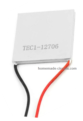
A Peltier device is a 2-wire semiconductor device having two surfaces that generate hot and cold temperatures across them in response to electricity supplied on its wire terminals.
Basically it works on the principle of thermo-electric effect (opposite of Seebeck Effect) where a potential difference is used for making or producing hot and cold temperatures over the two ends of a dissimilar metal assembly.
A Peltier device has two terminals in the form of wire ends which requires to be connected across a voltage source rich in current content.
The application of voltage instantly starts transforming one surface of the unit hot and the reverse surface cool very fast.
However, the hot end must be quickly managed so that the heat does not reach higher levels, which can completely hamper the heating and cooling process and ruin the device itself.
Therefore the hot surface must be attached with heavy heatsinking materials like aluminum or copper metal of suitable sizes.
How to Build a Simple Fridge using Peltier Device
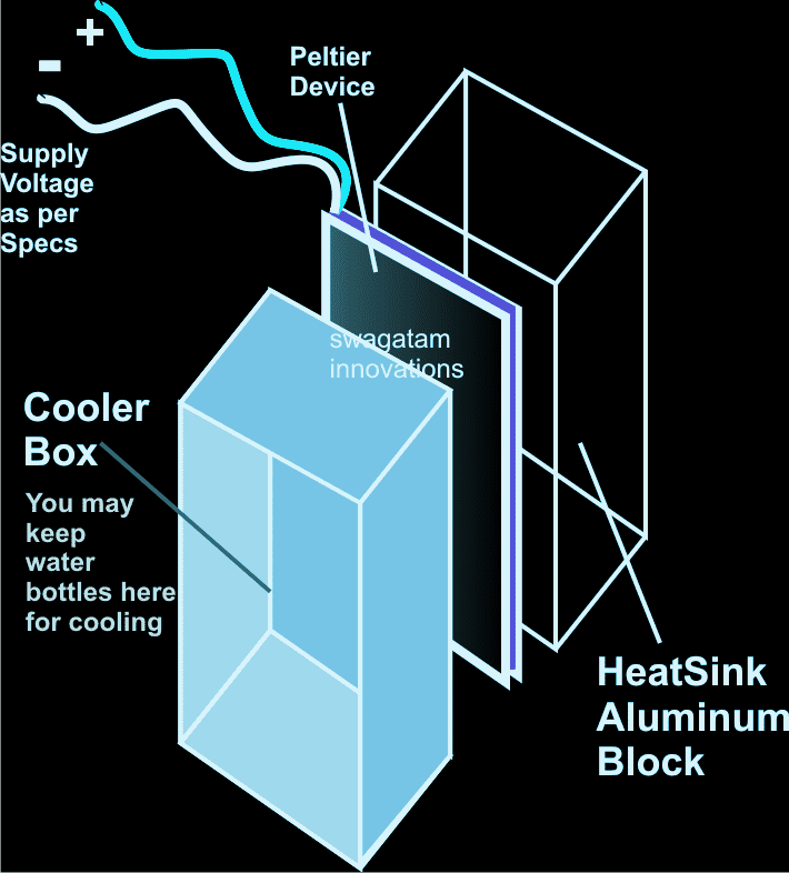
The simple construction of a simple peltier refrigerator circuit shown in the figure demonstrates the above discussed set up where two such devices are appropriately fixed with aluminum plates for radiating different degrees of temperatures from their relevant sides.
The plates responsible for generating the cooling effects must be trapped inside a well insulated enclosure made up of thermocole or polyurethane foam etc.
The inside chamber may be used for storing water bottles or water packets as desired.
The hot heatsinked surfaces must be exposed in the outside air for radiations and for controlling the temperatures of "hot" ends of the unit, see figure.
Complete diagram for understanding How to Make a Simple Peltier Refrigerator at Home.
Peltier Performance Specifications
- Hot Side Temperature (ºC) 25ºC / 50ºC
- Qmax (Watts) = 50 / 57
- Delta Tmax (ºC) = 66 / 75
- Imax (Amps) = 6.4 / 6.4
- Vmax (Volts) = 14.4 / 16.4
- Module Resistance (Ohms) = 1.98 / 2.30
Video Demo
Formulas for Calculating Peltier Parameters
Peltier Heat (Qp):
Qp = Pi * I
Where:
- Qp = heat absorbed or released at the junction (in watts, W)
- Pi = Peltier coefficient (in volts, V)
- I = electric current passing through the element (in amperes, A)
Thermal Resistance (Rth):
Rth = ΔT / Q
Where:
- Rth = thermal resistance (in °C/W or K/W)
- ΔT = temperature difference between the hot and cold sides (in °C or K)
- Q = heat transfer rate (in watts, W)
Temperature Difference (ΔT):
ΔT = Qp / Rth
Where:
- ΔT = temperature difference across the Peltier element (in °C or K)
- Qp = heat pumped by the element (in watts, W)
- Rth = thermal resistance (in °C/W or K/W)
Joule Heating (Qj):
Qj = I2 * Re
Where:
- Qj = Joule heat (in watts, W)
- I = electric current (in amperes, A)
- Re = electrical resistance of the Peltier element (in ohms, Ω)
Total Heat (Q_total):
Qtotal = Qp + Qj
Where:
- Qtotal = total heat to be removed from the hot side (in watts, W)
- Qp = heat pumped by the Peltier effect (in watts, W)
- Qj = heat generated by Joule heating (in watts, W)
Solving an Example Peltier Problem
Given:
- Peltier coefficient, Pi = 0.5 V
- Electric current, I = 3 A
- Thermal resistance, Rth = 0.1 °C/W
- Electrical resistance of the element, Re = 1 Ω
- Calculate the Peltier heat, Joule heating, total heat, temperature difference.
Step 1: Calculate the Peltier heat (Q_p):
Qp = Pi * I
Qp = 0.5 V * 3 A
Qp = 1.5 W
Step 2: Calculate Joule heating (Q_j):
Qj = I2 * Re
Qj = (3 A)2 * 1 Ω
Qj = 9 W
Step 3: Calculate the total heat to be dissipated (Q_total):
Qtotal = Qp + Q_j
Qtotal = 1.5 W + 9 W
Qtotal = 10.5 W
Step 4: Calculate the temperature difference (ΔT):
ΔT = Qp / Rth
ΔT = 1.5 W / 0.1 °C/W
ΔT = 15 °C
- The Peltier element produces a 15°C temperature differential between the hot and cold surfaces.
- The total heat that must be dissipated from the hot side is 10.5 watts.


Comments
Hi Nagaraj here again.
I have come across many YouTube sites giving details of making Peltier based AC and the one you are mentioning of (Fridge). But I don’t see them working properly. I used 12706 peltier, 12V/5A smps.
Can you help me in this by giving the necessary circuit if required based on the above info given by you.
Hi Nagaraj,
The fridge will work only if the heat dissipation from the Peltier device is managed perfectly, because the Peltier must not become hot otherwise it will fail to work. Please fix the Peltier device tightly over an large aluminum finned heatsink with lots of heatsink paste applied between the Peltier surface and the aluminum heatsink surface, if possible also use a small cooling fan to keep the heatsink from overheating, or you can also use water cooling on the heatsink.
No circuit is needed, just connect the Peltier with a 12V 10 amp DC supply and make sure the Peltier is thoroughly cooled and maintained at room temperature.
Very informative post, thanks for sharing your knowledge with us. I am considering building a simple camping cooler/refrigerator using a Pelletier device. Would it be possible to use the heat side to power a thermoelectric generator, thus supplying supplemental electricity to my solar array?
Thank you, and glad you found the post helpful! Yes, the heat can be used to power a thermoelectric generator for generating supplemental electricity.
Hi,
I am designing a variable controlled peltier cooling device. I would like to control 4 peltiers (individually) across their effective voltage range (~2v-18V) with incoming power around 20V. The resistance of the peltiers changes depending on their temperature in a range of about 3-4ohms. I am using mosfets, an arduino and a power filter utilizing a schottky diode, inductor and low ESR capacitor. I can control the frequency and duty cycle of the arudino output (using bitbang pwm) (my current thinking is a frequency around 18,000 Hz) but I am having trouble picking the inductor and capacitor values to appropriately filter the output. I was wondering if you could help walk me through the calculations to do this appropriately.
Hi, I am sorry, I do not have the required formulas and information with me at this moment, I wish I could help you!
Sir,
I was looking for a circuit diagram of ultrasonic generator which is used in making face masks. The Chinese are everywhere with their ultrasonic generator machine. IT will be a great help to me and others who want to make in India and help our country and society.
Thanks Anil, I am investigating it, if possible I may post a related article soon, so please keep tuned.
Dear sir, I am one of your readers. I want to read a post on home made peltier device. Your projects are really valuable for your readers.
Thanks Waagyi, I have already explained the concept in the above article, please go through it…..
dear sir,
please i am out of topic and i really want to build this for my home use where i live, i want to ask, how many volts DC can this fridge work with, then the most important equipment i will ask you is, what is the name of the part that is between the cooling heat-sink and the cooling box, i have never come accross a Peltier before, please if you can help me i will really appreciate it sir i am in need of your help, my email address is (dnkwenti@gmail.com)
have a nice day sir.
Dear Deogratia,
The power input will depend on thre Peltier device rating (watts) that you may want to use for your application.
Google "how Peltier device works" and you'll come across many good sites with detailed info…it's important that you learn everything before trying this concept.
Hello Kushal,
Please explain your requirement more elaborately,
….what is off mode?