In this post I have explained a cell phone remote control circuit using the light from its display. The idea was requested by Dondon.
Technical Specifications
I need a circuit similar to the circuit above but I will use the LED of mobile phone as light source so I can turn ON and OFF the load using mobile phone.
The load will be activated only after two rings of the phone, after 1st ring the device will wait for the 2nd ring within 2 or 3 minutes or else the 1st ring will be discarded to avoid unintended triggering of the load.
If possible the supply of the 4017 IC is 3.7V so I can connect it to mobile phone battery to preserve the output state in case of power interruption, the relay section can be connected separately to 12V so it will not drain the phone battery. Thank you Sir in advance and more power to you!
The Design
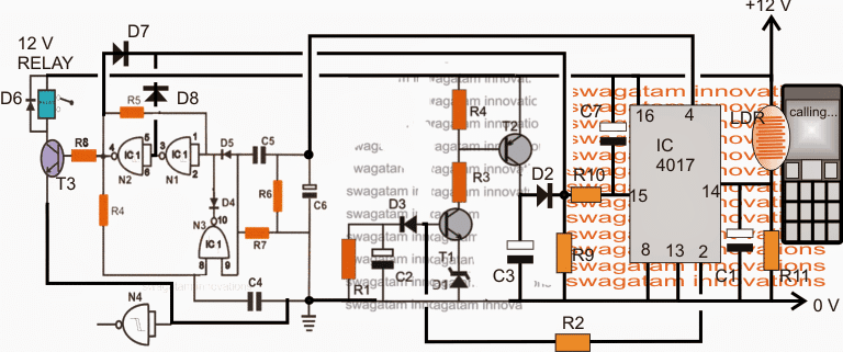
The proposed cell phone display light remote control circuit could be seen in the given diagram. The details may be understood from the following explanation:
The circuit basically consists of three stages: the left flip flop stage using NAND gates, the center delay ON stage using BJTs T1, T2 and the right side is a light detector and processor circuit stage using the IC 4017.
When power is first switched, the capacitor connected across pin15/positive of IC 4017 resets the IC making sure that at start up pin 4 and pin 2 of the IC produces logic zero.
Assuming the cell phone display to be inactive, the LDR is held at complete darkness ensuring a completely neutral and a deactivated condition of the circuit.
Now suppose a call is made on the attached cell phone, it's display illuminates creating a low resistance on the LDR which in turn allows a positive "clock" to strike pin14 of the IC 4017.
This forces the IC to shift its logic high from its pin3 to pin2. At this position the cell phone display light duration or the call duration become immaterial may be ignored.
However the high at pin2 begins charging C2 via R2 in order to activate the delay ON timer made up of T1 and T2.
Suppose no further call is made on the cell phone in this stipulated and the display is allowed to shut off, pin2 continues charging C2 until the potential level at the base of T1 rises to a point of saturation switching ON T1 and T2.
T2 collector instantly sends a positive signal at pin15 of IC 4017 forcing it to reset removing the pin2 high across C2 and restoring the IC to its previous standby position.
However, suppose while C2 was charging and before T1 could conduct another call was made on the cell phone, would have created another "clock" at pin14 of the IC4017, forcing its output to shift from pin2 to pin4.
In the above situation removing pin2 high prevents the delay ON timer from activating and its role is removed in this situation but the high shift at pin4 sends a positive pulse to the flip flop stage, causing the relay to change state either from N/C to N/O or vice versa depending upon its initial situation.
As soon as the flip flop engages itself and the relay into a flipped mode, a positive from the relevant output of either N1 or N2 is fed back to pin15 of IC 4017 resetting it back to its original standby position for the next triggering cycle.
Thus the relay gets successfully activated or deactivated for toggling the connected load ON/OFF with the above procedures.
All subsequent pair of calls made on the modem cell phone within the stipulated time causes the relay ON and OFF which in turn is used for toggling any suitable load across the contacts.
The unit may be considered to be entirely foolproof due to the incorporation of a timed and paired signal inputs from the cell phone.
Parts List
R1, R7, R6, R11 = 100K
R2 = 330K
R3, R4, R10, R8 = 10K
R5, R5, R9 = 2M2
T1, T3 = BC547
T3 = BC557D1 = 3V ZENER
D2---D8 = 1N4148
C1,C3 = 1uF/25V
C2 = 1000uF/25V
C4, C5 = 0.22uF
C6, C7 = 10uF/25V
N1----N4 = IC 4093
LDR = SHOULD BE AROUND 10K TO 33K IN CELL PHONE LIGHT


Questions & Answers
Sir plz use SG3525 pulse width modularitor and IRFP4568pbf and make a complete inventor and plzpost its diagram.. thanksss
Muhammad, such circuits are already posted in many other websites, you just have to replace their existing mosfets with the mentioned one.
please Mr. Swagatam I want a circuit using 4017 IC inwhich I manually change the squence using press switch.
Safiyan, you can try the following design, and modify it further as per your app specs
https://www.homemade-circuits.com/2013/08/single-push-10-step-selector-switch.html