In this post I have explained the circuit for a simple, universal capacitive discharge ignition circuit or a CDI circuit using a standard ignition coil and a solid state SCR based circuit.
For an audio/video explanation, you can watch the following video representation:
How Ignition System in Vehicles Work
The ignition process in any vehicle becomes the heart of the entire system as without this stage the vehicle just won’t start.
To initiate the process, earlier we used to have the circuit breaker unit for the required actions.
Nowadays the contact-breaker is replaced with a more efficient and long lasting electronic ignition system, called the capacitor discharge ignition system.
Basic Working Principle
The basic working of a CDI unit is executed through the following steps:
- Two voltage inputs are fed to the electronic CDI system, one is high voltage from the alternator in the range of 100 V to 200 V AC, other is a low pulse voltage from a pickup coil in the range of 10 V to 12 V AC.
- The high voltage is rectified and the resultant DC charges a high voltage capacitor.
- The short low voltage pulse drives an SCR which discharges or dumps the capacitor's stored voltage into the primary of an ignition transformer or coil.
- The ignition transformer steps up this voltage to many kilo-volts and feeds the voltage to the spark-plug for creating the sparks, which finally ignites the combustion engine.
Circuit Description
Now let’s learn the CDI circuit operations in detail with the following points:
Basically as the name suggest, ignition system in vehicles refers to the process in which the fuel mixture is ignited for initiating the engine and the drive mechanisms. This ignition is done through an electrical process by generating high voltage electrical arcs.
The above electrical arc is created through extreme high voltage passage across two potentially opposite conductors through the enclosed air gap.
As we all know that for generating high voltages we require some kind of stepping up process, generally done through transformers.
As the source voltage available in two wheeler vehicles is from an alternator, may not be powerful enough for the functions.
Therefore the voltage needs to be stepped up many thousand folds in order to reach the desired arcing level.
The ignition coil, which is very popular and we all have seen them in our vehicles is especially designed for the above stepping up of the input source voltage.
However the voltage from the alternator cannot be directly fed to the ignition coil because the source may be low in current, therefore we employ a CDI unit or a capacitive discharge unit for collecting and releasing the alternator power in succession in order to make the output compact and high with current.
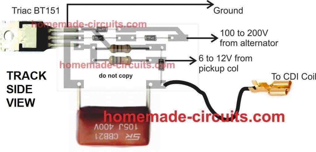
PCB Design
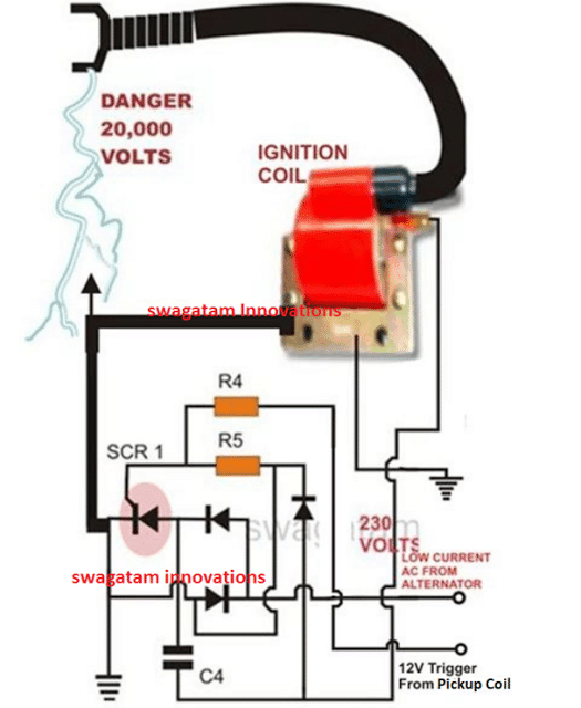
CDI Circuit using an SCR, a few Resistors and Diodes
Referring to the above capacitor discharge ignition circuit diagram, we see a simple configuration consisting of a few diodes, resistors, a SCR and a single high voltage capacitor.
The input to the CDI unit is derived from two sources of the alternator. One source is a low voltage around 12 volts while the other input is taken from the relatively high voltage tap of the alternator, generating around a 100 volts.
The 100 volts input is suitably rectified by the diodes and converted to 100 volts DC.
This voltage is stored inside the high voltage capacitor instantaneously. The low 12 voltage signal is applied to the triggering stage and used for triggering the SCR.
The SCR responds to the half wave rectified voltage and switches the capacitors ON and OFF alternately.
Now since the SCR is integrated to the ignition primary coil, the released energy from the capacitor is forcibly dumped in the primary winding of the coil.
The action generates a magnetic induction inside the coil and the input from the CDI which is high in current and voltage is further enhanced to extremely high levels at the secondary winding of the coil.
The generated voltage at the secondary of the coil may rise up to the level of many tens of thousands of volts. This output is appropriately arranged across two closely held metal conductors inside the spark plug.
The voltage being very high in potential starts arcing across the points of the spark plug, generating the required ignition sparks for the ignition process.
Parts List for the CIRCUIT DIAGRAM
R4 = 56 Ohms,
R5 = 100 Ohms,
C4 = 1uF/250V
SCR = BT151 recommended.
All Diodes = 1N4007
Coil = Standard two-wheeler ignition Coil
The following video clip shows the basic working process of the above explained CDI circuit. The set up was tested on table, and therefore the trigger voltage is acquired from a 12V 50Hz AC. Since the trigger is from a 50Hz source, the sparks can be seen arcing at the rate 50Hz.


Questions & Answers
Hey Swagatam Majumdar,
I have a Indian make yamaha Rx 135 (2stroke) and a TVS apache RTR 160.
These bikes have CDi's from the company itself.
Is it possible to enhance the performance of these bikes or a matter of any small cc bikes?
(P.S. I have read a lot about Performance CDi's and want to make one on my own. Please Guide me as this is very interesting topic for me)
Thanks,
Chinmay Bisht
chinmay20002@gmail.com
Hi Chnmay,
I have discussed one such circuit here:
https://www.homemade-circuits.com/2013/01/make-this-enhanced-capacitive-discharge.html
Although the circuit is a tested one and it definitely works, I am not sure if it would produce any adverse effect on the bike engine, you can give it a try under the supervision of a qualified auto electrician.
http://www.molla.org/DIY-CDI/SC-DIY-CDI-article-hires.pdf
That's a very interesting and useful link, thanks very much!
No, no specific limit.
when vehicle engine stops, the circuit also stops.
yes, if there are two spark plugs, then two CDIs can be used.
Hi sir… I have a honda dio 50cc 2 stroke scooter? Would this work instead of the stock cdi which has 5 pins and limiter?
Hi Ryan,
Yes the above circuit is a standard CDI circuit suitable for all 2 and 3 wheeler, basically it's an Indian, Bajaj 2E Rickshaw CDI circuit.
Hi Swagatam
What is the function of the diode connected across the primary of the ignition coil?
With cathode grounded, won't it obstruct the capacitor's energy from passing on to the primary of the ignition coil ???
Hi Abu-Hafss,
simulating the capacitor discharge pattern could be little difficult, however i am assuming the diode to be reversed biased, because practically the circuit is working perfectly so it means everything is right in the circuit.
It is also working without that diode !
did you test it?
Yes, the CDI of old model of Yamaha is 95% identical to yours, it does not have that diode.
the above circuit was designed by 'Bajaj" engineers, so the diode does work in someway to protect the longevity of the unit….because conditions in automobile electrical AC are too unpredictable, which show its impact in course of time and not immediately.
Hi I have a honda xr200 1981 the cdi is buggered will I need to get another one or is there a way to bypass this?
Do you mean damaged? it would be better to replace it then
Hey just surfing around the net looking at info on CDI design and implementation on the hobbyist level.
I have a 46 cc retrofit kit for a bicycle and it has given me 4 years reliable use even though it is very cheap engine that gets hard used.
I have had an alcohol still for a couple of years and have recently began running it on the head of the still 98% methanol 2% hydro-sol.
It has a magneto coil, I want a little more spark. I understand that i will need to implement a better cdi but also wonder if i can rewind the magneto coil or change the magnet provided there is enough room
yes making the magneto stronger would hep generating stronger sparks, so you can either modify the winding or simply procure a mobike magneto and replace it with the existing one,
Good day Swagatam Majumdar! I have a 2 stroke Yamaha L2GF 110 cc 1970's model that uses points. Can i convert it to cdi and use your circuit? Thanks..
Good day John,
Yes you can use the above circuit for your bike.
I am not clear on the trigger circuit, Can Hall Effect Sensor be added and a Transistor in place of the SCR.
hall effect/ transistor can be used for triggering the SCR, however it's more simply done directly through the AC received from the alternator 12V coil, as depicted across the diagram output terminals.
I have a need for an ignition system for a 6 cyl 2-cycle engine. 2 cylinders fire at a time, two times per revolution. i.e. that's 12 sparks per 360 degrees of crank rotation. I am quite gifted mechanically but alas, electrickery has me by the shorts. Can any reader offer assistance? Thanks, M8 (Mate)
you can try the following circuit,but could be difficult for you considering that you are very new in this field:
https://www.homemade-circuits.com/2013/10/universal-multi-spark-enhanced-cdi.html
Hello Dung,
It's quite easy, after making the above explained CDI circuit, you will just have to integrate the inputs to the indicated voltage outputs of the alternator.
Next, the C4 bottom link will need to connected with the free end of the primary of your ignition coil.
The other terminal of the primary coil will not require any attention as it would be originally connected to the ground of the vehicle.
That's all, this would conclude the installing of the explained CDI circuit
Hi Swagatam
I am making a CDI tester as per block diagram:
But, I am cautious that the pulse generator circuit might not be isolated from the 220VAC mains.
Your valued suggestions are requested.
Hi Abu-Hafss,
Do not use direct 220V, it can damage the diodes and the scr, you will need to isolate it using two step down trafos connected back to back
Hi Swagatam
Recently I physically made the 555 boost circuit with an output of smooth 600V.
The BJT network was removed. The Coil is super cool but the mosfet gets little warm.
However, when I feed the HV into the CDI………………..Nothing Happens.
1) If the triggering circuit is separated, the LED at the output shows perfect triggering. But when the output is connected to the CDI unit, the LED goes off.
2) If manual triggering is done with 9V battery/power supply, a faint single spark could be heard at the spark plug but not visible.
3) One point which might be or not important. The CDI unit is having 400V capacitor whereas, the boost circuit is producing 610V. Could this be the reason?
Hi Abu-Hfs,
What is the gauge of the wire that you have used? It should be selected appropriately for getting the required amount of current.
And the current from the power supply should also be rated high enough for the CDI coil to respond.
even 400V is high enough for acquiring 20000 volts from the CDI coil, so it's fine
I used 50 turns of 21 SWG (0.8mm) on a iron powder toroidal ring.
21 swg looks OK to me.
check the current through the coil and the BJT, this magnitude will actually decide the watts pushed into the ignition coil and will influence the sparks.
what is iron powder, do you mean ferrite?….ferrite core is a must for this application. iron core will only convert current to heat.
Hi Swagatam
I am operating this circuit with 12V-5A supply i.e. 60VA input.
The output is 600V, so the amperes roughly 100mA. This is just for idea. I will check the amperes and will inform you.
Ferrite toroidal rings are the black one whereas the iron powder toroidal rings are made with iron powder……more details could be seen here:
http://www.inductors.ru/pdf/Doc496_Ferrite&Powder_Core_Power_Inductors.pdf
I used Yellow/White ring.
Hi Abu-Hafss,
I think we are forgetting one thing, it's not the current that is important here, rather the voltage.
and it just requires an excess of 100V AC for the circuit to create powerful sparks across the high tension wire of the CDI coil.
Please refer to the first circuit given in this article, please see how it's configured:
https://www.homemade-circuits.com/2011/12/homemade-fence-charger-energizer.html
Hi Swagatam
The article you are referring involves 2 transformers whereas, my effort was to use a transformerless design.
I had that point in my mind that current is not an important issue here. For that particular reason, the output is around 600V as long as the input voltage is between 12V-30V !!!
Without the CDI, I have checked the capacitor gets charged within milliseconds. To connect to the CDI unit, I removed the capacitor + diode and connect the mosfet+coil directly to HV input of the CDI unit. (The CDI has its own diode and capacitor).
At the HV input the DVM set at AC is showing 6-7 volts !!! How can that be??? The CDI unit works perfectly in its place.
Hi Abu-Hafss,
I referred you the above circuit to indicate how the low current 220V input from an ordinary trafo works perfectly to produce the required 20kv sparks at the output of the CDI coil
I am afraid removing the diode capacitor network will not help, it's required for the proper functioning of the design, may be because it operates by charging and releasing the capacitor stored energy only when the capacitor charge reaches some optimal point.
The think the CDI coil or any such trafo responds best when bursts of high voltage are dumped in their primary winding instead of a continuous frequency.
Hi Swagatam
It seems to be quite difficult in getting the 555 boost circuit to work as HV supplier to a CDI. I have spent many hours but, not successful.
Presently, since I need the HV supply only for bench test unit for CDIs, I am considering to use a transformer.
I have a 220V-13V 100mA small transformer. Will it be okay, to use it with a 555 astable oscillator at 50-60Hz + TIP31C? Or do I need to have a bigger transformer?
Hi Abu-Hafss,
A high frequency input will not work with a CDI coil, you will have to use the converter in a burst mode or a pulsed mode, and it should match the input winding voltage rating of the CDI.
A 100mA transformer will also work but again it needs to be operated in a pulsed mode that's why the diode/capacitor stage becomes so crucial.
Hi Swagatam
1) If we use the diode+capacitor before the CDI, the HV would turn to 600VDC whereas the CDI needs an AC voltage to operate.
2) As far as the 100mA transformer is concerned, I simply followed your circuit
https://www.homemade-circuits.com/2013/01/make-this-enhanced-capacitive-discharge.html
only replaced the darlington with TIP31C. I could get only 130V which, if fed into the CDI results nothing.
3) As per your above statement if diode & capacitor are crucial then how your enhanced CDI worked without them?
4) I also tried this
https://www.homemade-circuits.com/2012/02/how-to-make-simplest-inverter-circuit.html
replacing 2N3055 x 2 with TIP31C x 2 and 12-0-12 200mA transformer.
The voltage at primary is 24VAC but the voltage at the secondary is less than a volt!
Hi Abu-Hafss,
All my CDI circuits have a high voltage capacitor stage included, which one exactly are you referring to?
Hi Swagatam
I think you got confused with my long message.
Please see the attached picture:
1) With HV Supply 1, I could get 600V. The diode and capacitor has to be removed, only HV AC has to be fed into the CD unit. But the set-up did not worked as I reported on my post of Feb. 7th.
2) I tried HV Supply 2 and 3, got only 130VAC but again the set-up did not worked. This set-up is based on your article of enhanced CDI for 2-wheelers.
3) The HV Supply 4 is based on your article Simplest Inverter with 70% efficiency but this also not worked, I could get less than a volt.
The High Voltage Capacitor you are referring is already included in the CDI unit. I am not talking about the CDI unit (it is untouched). I have been talking about various set-ups for HVAC supply which has to fed into the CDI unit. I hope now everything is clear. Now I await your valued comments.
Hi Abu-Hafss,
The circuit shown in the following link worked very nicely for me:
https://www.homemade-circuits.com/2013/01/make-this-enhanced-capacitive-discharge.html
You can make this circuit exactly as it's shown and then compare it with your designs and check why this one works and your designs don't.
I think the gate trigger could be the culprit.
Okay, I'll start all over again.
But what do you say about the HV Supply 1?
Hi Swagatam
Today, I re-started the project from beginning.
Firs,t I checked the HV supply in a bike, I found it to be 125VAC.
Second, I checked the CDI unit. It was working fine.
I rebuilt the circuit same as yours, only changed the RC components to fixed values to get 51.50% duty cycle and 57.75 Hz frequency. The output was 136V.
When I connect these 136V to the CDI unit, they dropped to 40V. But I could not get any sparks at the spark plug 🙁
Hi Abu-Hafss,
Where did you connect the SCR gate terminal of the CDI (the 470 ohm end with reference to the linked circuit)?
Hi Swagatam
First I connected the triggering input to the output of variable frequency oscillator (max. 5V). When I could not get the sparks, I manually tapped the triggering input with 12V but still no sparks.
Hi Abu-Hafss,
Something is surely wrong somewhere, I think for avoiding doubts you could try following the exact design that's been shown in my circuits, and also use the same ignition coil which has been shown in the drawings.
Hi Swagatam
I checked the coil and found that the secondary has very high resistance in M-Ohms, maybe due to the high tension wire, though it worked perfectly in the bike. Anyway, I bought a new one same the one shown in your drawing. It had perfect reading of about 6k.
However, as reported on Feb. 15th, when I fed 136V thru CDI to the new coil the voltage dropped to 40V and there were no sparks.
Hi Abu-Hafss,
I am not sure what could be the problem, because the circuit is too straightforward and should start working immediately, I have already made this circuit for many different applications and everytime it responded correctly.
You can try the fence charger design and see if it works for you or not.
https://www.homemade-circuits.com/2011/12/homemade-fence-charger-energizer.html
One more point………….
When I switch on the circuit the LED connected to the pin#3 of 555 would indicate the oscillation. And sometimes when I connect the transformer, the oscillation would stop.
In other words, sometimes when the transformer is connected to the collector of TIP122 and the +ve rail, the 555 would stop oscillating. And then when I disconnect the transformer, it would resume the oscillation after some time. This does not happens every time.
However, the problem I reported earlier occurred when the 555 was oscillating with the transformer and the output 136V.
Lastly, please remember the transformer I am using is 12V 100mA.
Hi Abu-Hafss,
try the fence charger design without the 555 stage, let's first make the basic design work ad then you can proceed with the other versions.
I think the second trafo should be rated a little higher, may be a 500mA will be more suitable.
Hi Swagatam
Your drawing is bit confusing, I have simplified and reproduced it.
Please check and confirm, if I have understood your circuit correctly.
Hi Abu-Hafss,
It's one and the same, to me your diagram looks more confusing:) because in my diagram the bridge is well isolated from the transformers and makes it clearer to understand that it's been installed for powering the 555 circuit.
HI Swagatam
Finally, I have managed to get the tester working with the fence charger configuration without the triac. Actually, I got deceived with the earth sign in your schematic. I separated the negative supply for the CDI + ignition coil and the triggering circuit. However, the sparks are quite weak. I am considering to replace the 2nd transformer with a 6V so that the output is around 400-440V.
Hi Abu-Hafss,
That's great! In DC circuit, the earth symbol generally indicates the common negative rail.
You can also try a 1amp transformer for the one which is connected with the CDI, this could also help to increase the spark strength.
Hi Swagatam
Yes, the earth sign generally indicates the common negative rail, that's why I mistakenly assumed that the 555 is also grounded to that negative rail. Shouldn't I advise you to point out this important note in your article so that people like me may not get deceived.
Right now, I am using 2 x 12V 250mA xformers. I think changing the 2nd xformer to 1A won't strengthen the spark because the sparks are released from the charge dumped in the capacitor. Therefore more higher voltage will result strong spark.
Hi Abu-Hafss,
I'll remove the earth symbol so it doesn't confuse the new hobbyists.
Higher voltage will produce longer sparks but will be weaker in power (not very bright), increasing amps will make the sparks thicker, stronger and brighter.
Hi Swagatam
Ok, but in that case both the xformers should be changed………because the output from the first would the input for the 2nd. If only the 2nd is changed, the input wattage would remain the same and hence the output would remain the same.
Hi Abu-Hafss,
Yes that's true, you will have to change both the transformers with 1amp
Hi Do you have a CDI circuit that will work for my +ve earth motorcycle which will run from 12 volt battery and points. Thank You Peter pnptrudgeon@gmail.com
Hi, the body polarity is irrelevant here. You can use the above suggested circuit with your vehicle also….just make sure the "earth" lines of the circuit are only connected with the battery negative and not with the body of your vehicle.
Thank you much appreciated. Best Wishes Peter
how to make a adjustable cdi for 180cc 4 stock or can i modify the existing
what do you want to adjust?
Dear sir,
what happen if we changing C4 (1uF) to bigger 220uF 250V?
thanks
Dear Nuraniku, it's not recommended, and moreover it would produce the same results as with a 1uF/400V….however, the capacitor will need to be a nonpolar type.
As Sawagatam said, it is not suitable because a 220µF capacitor would take longer time to charge as compared to a 1µF capacitor which would fully charge within nano seconds!
hi sir,
i want to build this circuit,but my question is how can i connect this,,
is it alternator ang magneto are the same?
i found a magneto coil to rectifier on my bike,where i connect this from your circuit?
pls
hi nhark,
yes alternator refers to the magneto in your bike…
locate the 200V and the 5 V to 12 V sync pulse coming out from the magneto and connect them with the relevant terminals of the above circuit, also connect the shown outputs with the ignition coil and the coil output with the spark plug….the circuit will start working immediately.
hi sir,
i built one this day but it can not start the engtine…why?
hi nhark, the problem could be in the circuit assembly or the wiring connections with your bike.
tnx sir…it was my mistake…
hehehe
Hi sir
i want high voltage from this circuit
like 300v to 400v.
Kindly tell me how tjis possible
Hi Mansoor, the CDI coil in the above circuit is capable of producing 20,000 V and is intended to be used in automobiles…
Hi sir thank you for replying.
actuall i mean to say that the above circuit output voltage is 230v to going on ignition coil,
And ignition coil 230v to become 20,000 v.
But it can possible circuit produce 400 V and forward to ignition coil.
And then ignition coil 400 V to become 40,000 Volts?
I wana ask you one question.
And question is
Do you built any plasma ignition circuit?
As you know plasma ignition very much powerful spark.
and its circuit takes dc HV from battery.
Hi Mansoor,, It can be tried but forcing 400V into the coil could make it hot.
making a plasma spark will require a much bigger coil….possibly I'll post the article someday in my blog
Dear sir,
My bike is honda cd 125 and its 10000 rpm
and its ignition build for 10000 rpm.
i am customize engine for 15000 rpm and its require improved ignition.
does above circuite use for this 15000 rpm
Dear Mansoor,
yes according to me 15000 RPM will not be a problem for this circuit since it uses a fast, and advanced SCR for the switching.
Its mean this SCR BT151 competible for 15000 RPM
yes it is…
If we alter some parts change for earn more voltages like 400 V to give ignition coil.
like AC alternator 12v and 1amp change to direct DC 12 V battery input and circuit's change diods 1N007 change to 1N 5408 – 3amp doids.
Does it run and genrate more voltages and more power?
increasing voltage or current won't do any good for enhancing the automobile performance because the spark plug gap is too small and will respond equally to a low voltage or a high voltage…..
The ignition coil and the circuit is already powerful enough, to produce sparks 1/2 inch long….it implies that you could try altering the spark plug gap and make it about 1/2 inch long,,,,this alteration could help the cause…..because longer spark would mean longer area covered by the spark inside the chamber influencing bigger explosions.
Thank very much
you can use a momentary on switch to temporarily ground the signal from the alternator, disabling spark and therefore stopping the motor. kill switch 🙂
can you tell me what voltage i should expect from the small 2 stroke ignitions used in made pales boat cars etc
usually 23 cc to 35 cc
Zenoah or chung yang
also the zenoah engines use a primary and secondary coil where as the CY uses a single coil
what are the differences between the 2
sorry I have no idea of these bikes…
normally a 2 stroke ignition would be able to produce 10kv
If i want to use this ignition in a 4 stroke 90 degree V twin, can i just use 2 pickup coils 90 degrees apart, hooked to 2 separate ignition boxes? Thanks!
I am not very sure about it, but you can definitely try it out
Not sure if my message went through as my computer is a little crazy at the moment.
CDI unit C4 capacitor, is it polarized or non-polarized?
I plan to try it on a Mercury outboard 402hp (40hp) motor, stator input is 180volt and trigger is 20volt, do you think it will be ok?
C4 is a non-polar capacitor, the circuit is intended for all 2 or 3 wheeler automobile engines, if your system similar to these engines then it'll surely work.
Is there a way to make this adjustable to change the spark timing ?
you can try the modified version of the above for achieving the timing feature
https://www.homemade-circuits.com/2013/01/make-this-enhanced-capacitive-discharge.html
Hi I have a 2005 suzuki gsxr 400 slingshot gk76 and can't find a cdi in south Africa and need to build my own if you can help whit that please
Hi, you can build the one that's shown in the above article, it's a universal type and is suitable for all 2/3 wheeler vehicles.
Hi Pieter
Your GSXR 400 is a heavy bike with high RPM. I am afraid the CDI discussed here is suitable only for smaller bikes 70-125cc. It might work with your bike at low RPM but at high RPM it will fail to synchronize the sparking. The OEM CDI unit for your bike is based on a micro-controller which delay the sparks at high RPM.
If you have no experience of programming/burning micro-controllers and want to get the job done without any hassle/frustration, I would suggest you to buy the original or compatible CDI from eBay or AliExpress. If you still want to DIY, let me know I'll forward you the link.
Hi Pieter, you can try the above circuit by replacing the CDI coil as per the specs, and under the supervision of an expert automobile engineer, the above circuit design is a universal design and can be used fr all conventional motorcycles with some modifications.
here's the image of the CDI coil for your bike
i.ebayimg.com/00/s/MzE0WDU0MA==/z/wYYAAOxy0rZRGSaP/$T2eC16R,!zEE9s3!%28Y1TBRGS,PgmwQ~~60_1.JPG?set_id=8800005007
it has a twin coil it means you can try making two of the above circuits and integrate the triggers with the relevant pick up inputs and the outputs with two spark plugs.
Hi,
I'm wondering If u have a printed circuit for this shematic.
(I'm not good at all on that software to make circuit)
If u have please share with us
Regards
Otto V.
Congrats for this page!
thanks otto, I had the PCB design some time ago, but have lost it now, so I am really sorry…. presently it would be difficult to post it back.
Hi
hi swagatam, can we replace the bt151 with a 2n3055 instead? also what is your opinion of bedini radiant charging oscillators, have you tried to replicate one yourself with useful success?
Hi Fidel, BT151 is a thyristor, which is completely different from a transistor and therefore the two cannot be replaced with each other….
no, I haven't yet tested the bedini charger, however i feel it could be true since it uses a flywheel concept and we all know how efficient a flywheel can be in terms of output vs input power
thanks for taking time to reply me mr swaga, I hope a man with such great knowledge in modern electronics concepts can build one test for yourself and give us your honest opinion based on the tests, regards!
it is important I also stress that we endeavor to investigate such devices at these times when the whole world is reliant on the $$$ guzzling oil and no one gives much thought about clean energy concepts seriously
I appreciate your thoughts Mr. Fidel, you are right, somebody must take serious initiative and prove the world about the potentials of these efficient machines…in my free time i would certainly want to go ahead and test one of those…
HI Swaga, just wondering the BT151 leg configuration>the BT151 Chip number label facing us: 1st leg-cathode(positive out) , 2nd leg-anode (positive enters), 3rd leg-gate..is this correct?
Hi fidel, that's correct!
Hi, i have a kawasaki kdx 220 that does not have a trigger coil! Will this schematic work on it? Thank you.
Hi, without a trigger coil no CDI can work for a motor bike as far as I know…so the above circuit will also not work without a trigger from a pick up coil
3 wires come from magneto, output, ground & lights! You can advance & Retard the stator plate! Could the trigger be in the cdi?
Hi Kevin
Kawasaki KDX-220 has trigger coil because this bike has CDI ignition. See the picture in the link below:
KDX 220 magneto has 2 coils, 12V for the electrical system and HV-AC for the CDI. Three wires means 12V, 180VAC and common ground.
Hi
If your bike does not has the trigger coil then most probably it has the points/condenser based ignition system.
In that case, you can use your points and the capacitor together with a 100Ω/5W resistor, in place of the trigger coil. Please see the link for the diagram:
The resistor is to be connected to 12V from ignition. This resistor provides wetting or whetting current for the points to ensure that there is good contact between the two contact-points when they are closed. This wetting current is sufficient to keep the contacts clean and avoiding and damage to them. The output is to be connected to the Pulse Input of a CDI.
Kevin,
Mr. Abu-Hafss will guide you through the required procedures
I have a 1980 4cyl 4 stroke kz 1000 that the ic igniter has become lost due to moving. I was wondering since it is a wasted spark system in which two plugs fire simultaneously can I build my own cdi to use in place of the ic igniter that was used originally? This question is brought about because of the rarity of factory replacements and the high cost of aftermarket replacements. If you have any ideas that will help please blueprint the for mentioned schematics, I will be more than grateful for any help.
There's no harm in trying the above shown design for your bike.
you can try making two such circuits with two separate ignition coils…and connect the relevant connections with the appropriate sources from the bike.
The system will certainly allow you to use your bike normally, if not at extreme high speeds.
Thank so much. I made this like cdi by bigger thyristor and without R4 resostor. Its better than original.
Pave from Finland.
thanks for the update
I mean that its better than scooters original cdi. Trigger pulse is only 5 volts in my scooter ( oskilloscope ). Therefore I made it without resistor. Its too low voltage for original cdi. This handmade cdi working very well. Thanks!
OK I am glad it's working for you! however a resistor is a must at SCR gate, even at 5V the SCR could destroyed if its gate is not protected with a resistor….you can use a 100 ohm resistor
Sir I want to make all Indian bike cdi unit can u provide me all solution like making n testing source….9015693522
Shinam, CDI circuit is provide in the above article, a CDI tester circuit is also included in this website you can use the search box to find the same.
Hi, i have a honda spada vt250 v-twin engine, i got a problem with my cdi some parts are burn and i dont know the value, do you have any idea with this or do you have some schematic diagram with it..? Please help me.. Thank you
ps. the burned parts which i recognize is diode i dont know the value, and the other one is a circle shape and it is badly burned. Thank you..
Hi, if you can show me the pics of the burnt parts I could try to identify them, if these are diodes then most probably these could be 1N4007 diodes…if the size is bigger then it could be a 1n5408 etc
If this circle shaped part has four legs then it could be a bridge rectifier…..
You can try the following:
ignore the ground connection of the CDI, meaning don't connect the indicated line of the CDI with the bike ground or body….and instead connect the two wires from the alternator with the 230V input and the ground line of the CDI
this is what I believe should work, but I am not sure about the socket connections, you may have to connect the wires directly with the above explained CDI and not through the socket.
It is the recommended one, and the best one as far long lasting concerned. others won't last for very long
Hi
If I make this Cdi box on the scematix
Will it work on my Ktm lc4 640cc
It will work for all general bikes, not with special high speed bikes which are intended to be used for racing or for extra high speed operarions….
Hello Swagatam, I came to this very helpful blog, while researcing a CDI for a medium displacement two stroke bike, and I have a very high regard for your availability.
Could you please elaborate a little, on the last statement of your last reply (July 30).
The engine I will hopefully use the CDI is of this kind (high power to weight ratio), so could you hint to the posssible paths to take, to achieve such an improved (battery-less) ignition?
Electronic advance, more current etc.
Thanks very much.
Thanks Roberto, actually I said that the above circuit is not intended to be used with high performance bikes, it's only for ordinary 4-strokes bikes which are meant for city use…although I have tried to develop a CDI with advance/retard features, it needs significant improvement until it could be applied practically, you can see it in the following article
https://www.homemade-circuits.com/2015/05/adjustabe-CDI-spark-advance-retard.html
Thanks
Hi sir.
Recently I made this circuit on a 2stroke motorbike, 50cc, improved performances for amateur racing. At idle the system works ok, but when I try to rise r.p.m. the spark goes off, I just can increase about 500 or 1000 r.p.m. from idle.
Whith the oem CDI system, it works ok, so the AC generator and pulse signal, I think its ok.
To test it, I mounted the circuit on a protoboard to experimental circuits, It could be this the reason? I tried to improve the continuity of the wires, betwen the ignition coil and the capacitor and also mass, with double or triple wires, but I didn't reach any result.
Comparing to the oem CDI, the spark if less powerful in this ciruit, I don't know if this could be the reason.
Thank you.
Hi Vincent, which SCR did you use?
make sure it is BT151 from Philips.
If you think spark power could be the cause you could try increasing the value of C4 to 2uF/400V and see if that makes a difference.
Hi Mr. Swagatam!
I use a BT151 650R but NXP.
I tried to increase the value to 2uF/400 but not with one capacitor, just mounting four capacitors 400V in parallel to arrive at 2uF. But the problem persists.
Thanks.
NXP is Philips, so it's fine.
the spark will be weak if the capacitor does not charge properly due to insufficient pulse width from the pickup.
may be the 1N4007 are not able to handle the high speed pulses and not conducting quickly to charge the capacitor fully….you can try replacing all the 1N4007 diodes with BA159 and check the response.
Hi Swagatam and Vicente
Since this CDI is an AC type (means HV AC is being supplied by source coil inside the magneto) the frequency of the AC voltage is not very high. 1N4007 should work perfectly.
Vicente, could you please draw the circuit diagram of your prototype? And provide a photo of your circuit? Actually, the circuit is quite simple and should work if the connections are made correctly. For SCR, 2P4M also work perfectly in 50-100cc bikes.
Hi Abu-Hafss, yes a high speed may not be required since the RPM is not in the kHz range.
We can assume the circuit built by Mr. Vincent to be correct since it is responding well at lower RPMs, and failing at higher RPMs.
I think the pick-up coil output has something to do with the issue
Hi, I used 1N4004, I think it's equivalent to BA159.
Also when, the r.p.m. increases, the pickup pulse width decreases, really, but mounted the OEM CDI, the system works ok.
Another question: how could I change the time since the pick up sends the signal, to arrives at the SCR? It is very interesting, beacuse I'would like to change or adjust the spark timming, in order that this circuit provides the spark too early, about 20 degrees before the original system, and this can be bad to the engine.
I'll continue working on this project.
Thanks for the circuit, to you and all the people that participates here.
Hi, 1N4004 is not a high speed diode, but anyway high speed diode may not be required.
sorry I mistakenly related the charging of the capacitor with pickup pulse, actually the pick pulse is related to SCR triggering not the charging of the capacitor.
Upon checking the waveform images, I found that increasing speed results in the increase of amplitude or the peak voltage output from the pickup, so how this could be affecting the SCR conduction is something that needs to be diagnosed.
You can try feeding the pickup output to a small bridge rectifier and connect the output from the bridge to the SCR gate….see if this hack improves the results.
spark advance retard could be a complex affair, I have tried to address this in the following article through a circuit concept
https://www.homemade-circuits.com/2015/05/adjustabe-CDI-spark-advance-retard.html
Ok, thanks a lot.
I'll try to improve my connexions, change several components, other pick up, etc.. and maybe, change motorcycle. I'll inform you.
OK great, thanks!!
Hi! here there are some pictures of my circuit, maybe any one can identify any defect.


If it is possible I'll continue this afternoon working on it.
Thanks.
Hi, verifying all the connections could be difficult and time consuming…but among the parts the capacitor quality looks suspicious….use an original philips make capacitor and see the response
use a bridge rectifier between the pickup input and the SCR gate
Hi Vicente
If I were you, I would have assembled on a 2" x 2" veroboard. But anyway, your connections seems to be OK. To me, the SCR looks doubtful.
By the way, can you get the waveform of the pulser input? I doubt if the pulser coil on your bike issues negative pulse first, then positive pulse. If that is the case, you might need to make some modification in the circuit because this circuit is designed to fire on a positive pulse.
Please see the difference between two wave patterns:


Hi Swagatam, I am from the Philippines and my motorcycle's cdi got damage lately. I have an old honda C-100, thanks to your cdi design it is running again. I have used a 1uf/450V capacitor instead of 1uf/250V because there is no available 1uf/250V on the store. will it affect the performance of the cdi? and I also hear small clicking sound comming from the circuit, is that ok? I have already traveled around 250km already using your cdi design. Thank you Swagatam Majumdar.
That's great Christian, I am glad it's serving the purpose for you!
If the max voltage from your alternator is below 200V then the 1uF capacitor can be rated at 200V without issues but if you are not sure and doubt that it might rise above 250V then you better change it to a 400V rated capacitor.
Any kind of sound from a solid state circuit is not good, you can check if anything's sparking or arcing at any place within the pCB.
Hi i am hassam from kashmir . i have suzuki's very old model gs250 fw with 4 cylinder engine i got a some problem with its cdi its not working good can i replace it with some thing r can repair it ? I m very far away thats why i can't get it new one its not available here i m going to import it i gonna bebe so expensive what should you suggest me…thanks
Hassan, The above CDI is a universal model which is presently being used in reputed Indian motorcycle brands such as Bajaj, and Hero Honda, so you can build this CDI for your motorcycle also and use it for the time being until you find the original version for your specific model…
What size resistors do you use for this CDI? 1/4W, 1/2W, 1W, Higher? Also, having trouble finding a 56 Ohm resistor locally, ant alternatives? Thanks!
What size resistors do you recommend for this CDI? 1/4W, 1/2W, 1W or bigger? Also, I'm having trouble finding a 56 Ohm resistor locally, and alternatives? Thank you!
you can use 1/2 watt resistors although 1/4 watt would also work.
56 ohm is not critical, you can try try 68 ohms, or a couple of 33 ohms in series
Will this work for a Suzuki RM 125? Also, I have 4 wires coming out of the stator, which wires connect to the CDI? Thanks again!
Also, What kind of capacitor do you use? Ceramic disc?
The trigger voltage on an RM 125 stator is only .3 Volts, will I need to remove R4?
the CDI can be used for all motorcycles as long as it is driven at a standard speed, not at racing levels.
please consult a motorcycle mechanic for confirming the wiring details….the capacitor is a PPC or MKT type
…your 0.3V reading is incorrect it cannot be that low….please consult a technician.
I'll check into the coil for the trigger… The max RPM's on this bike are 11,500. The four wires are + and – 25V primary coil and + and – for the trigger (according to some reading should be 3-5V). Assuming the (-) get tied to ground? What would be the minimum voltage needed for the trigger? Thank you, you have been a great help. I'm gonna give this a try, If it doesn't work at least I'll have fun trying it 🙂
5V will be enough for triggering the SCr, but the other supply which is supposed to go to the capacitor and the ignition coil must be around 60 to 100V, otherwise the spark strength can get affected causing inefficient combustion of the engine.
By the way 11500 RPM looks very high, not sure whether or not this CDI will be able to handle it.
I appreciate your willingness to try this circuit…wish you all the best.
Hi Swagatam,
I really enjoyed this article though I felt a bit lost in certain parts because even though I like electricity and electronics all I know I've learned "the hard way" ':). But my question is how do certain cdi's defer from other brands? Like I would like to apply this on your article to my yamaha dt125r but my bike is a bit of a transformer because it no longer has many stock parts. Like for example here in my country is very hard or very expensive to get original or oem parts, so I managed to make the bike rub without a cdi but I feel it is not as precise as it should, and the trial and error cost me a few more parts. In case you are interested what I did was i took out the pin on the crankshaft that allows the flywheel to be in the correct position so I could advance it or retard it, and so I plug the source coil wire directly to the ignition coil and placed the piston at TDC and made a small mark on the crankshaft to know when it is in TDC and also on the flywheel for reference, then I tried to kickstart the bike (it is a 125cc 2stroke) and if it didnt work i moved it bit by bit to find where i would get a kind of good spark but sometimes I got a recoil from it and made the engine run backwards, when it was a bit off of TDC it was not a problem because it would just run back instead of forward x) But if it was too close to TDC the recoil would crank the kickstart so hard it would break a few things, but it was fun though. So back to my question I would love to find a way to make my own CDI for my bike what specs would I need of the bike itself so I could build one?
Thanks in advance and best regards,
Thanks Robert,
I too enjoyed your adventures with your motorcycle and it clearly proves your innovative nature and skills. Since automobile is not my main field of work, I tend to forget quickly anything that I try to grasp in this field. Therefore I could not understand much the mechanical modifications you did in your bike.
However I am pretty sure that if your bike could work without a CDI then definitely it would do much better if the above explained CDI circuit was installed in your bike. Because the above design is an universal design and can be used for all regular bikes which are presently running on the roads throughout the world.
No doubt about it, and you can easily do it by assembling the little number parts indicated in the diagram, and simply hook them up with your bike's electrical.
I am sure you will be able to build the circuit and implement it successfully…. if you have any difficulty with the testing of the circuit, do feel free to post it here, I'll try to solve it out for you…
Hi Robert
Answering your question, the shape of the CDI unit is not important. Basically, there are two types of CDI unit i.e. AC-CDI and CD-CDI. Two different CDI units, different in shape/size for two different bikes can have same circuitry.
As you mentioned, if your bike has a source coil with high voltage output (about 180VAC) then the above circuit would definitely do the job provided the connections are correct.
Hello
+Swagatam Majumdar,
I was curious if this application can be used in a single spark small 66cc 2 stroke motorized bicycle? I have no battery and engine is "push started" by release of clutch which spins the "magneto" which i assume acts as an alternator would but on a smaller scale. I have not measured the output of the magneto to the CDI that comes with this kit but I wish to get the best performance possible. I have a faulty CDI that does not produce enough to get spark from plug that is necessary. It is a solid state CDI. do you think that I could open it up somehow and upgrade the components and or repair this thing so it would work?
I apologizes all this circuitry stuff is pretty new to me.
thank you for your dedication and your willingness to share your vast knowledge! You are very inspirational in my desire to further understand circuitry and the whole bit!
Reguards, David
Thank you David for posting your question and trusting my knowledge. If you are new to electronics then definitely you would find it almost impossible to troubleshoot or repair any faulty electronic unit…moreover since it's a solid state version would have more sophisticated parts than what is presented in the above article.
The CDI explained in this article looks an ideal choice for your requirement, and in fact can be used for generating sparks on any vehicle that may be equipped to generate a minimum 60V AC, and has a pickup coil.
The 60V is used for activating the ignition coil which ultimately generates the high voltage for the sparks. The pick coil responds to the wheel rotation and triggers the CDI to generate the high voltage pulses at the same rate as the wheel rotation.
Even if the pick coil is absent, the high alternator output can be suitably dropped and used as the triggering source for the CDI coil.
So basically if your bike possesses the above then you could easily exploit the above design in your favor.
Hi David
The above circuit should work with your 66cc bike without any problem. However to ensure correct operation, it is advisable that you send us a photo of inside of your magneto.
Thank you Swagatam + Abu-Hafss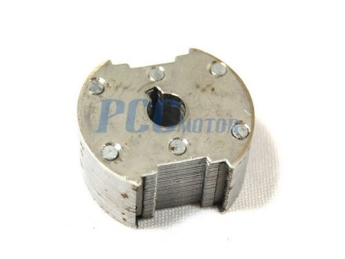
Thank you Guys for replying so quickly to my question!
Abu-Hafss- Are you asking for a picture of the magneto itself or a picture of the coil and how it is wrapped under the protective sheathing? here is a link to one like mine i found on ebay. i.ebayimg.com/images/g/NaMAAOSwR29ZE5We/s-l1600.jpg the magnet looks like this
if you need a picture of the coil of the magneto let me know and i will cut off the sheathing on an extra one i have and send you a link.
thanks again for your assistance!
one more Q: can all of the components that are required for this build be purchased at radio shack? Or is there a better place to acquire these types of special parts that you guys go to for items such as these?
I am having trouble locating the R4 = 56ohms is this a resistor? which is better to use a ceramic or ?? i found a 60Ohms resistor will this work?
http://www.allelectronics.com/category/530300/resistors/power-resistors/1.html
Thanks David, the ebay image is not opening for me.
the 56 ohm is a 1/2 watt resistor….however the value is not so critical, you can use any nearby value, such as 68 ohm, or even 100 ohm will do.
it can be as shown below:
projectpoint.in/thumb.php?f=image/data/CFR_1W_56E.jpg&w=400
60 ohms will work but try to get a CFR type as referred in my above comment, a wirewound type would also work but it's not necessary
Hi Sawagatam
I cannot see the following post (+ posts after this) in your blog despite of repeated reloading of the page:
Thank you Swagatam + Abu-Hafss
Thank you Guys for replying so quickly to my question!
Abu-Hafss- Are you asking for a picture of the magneto itself or a picture of the coil and how it is wrapped under the protective sheathing? here is a link to one like mine i found on ebay. i.ebayimg.com/images/g/NaMAAOSwR29ZE5We/s-l1600.jpg the magnet looks like this
@DAVID — Yes I wanted to see the coils inside the magneto cover. Anyway, I understood your required CDI is 2-wired self-triggered type used on motor-bicycles. That is slightly different from the one discussed in this article.
I shall post an article for that CDI but it might take a week or so, as I am bit engaged these days. I hope you can wait for a few days.
Oh Sorry Swagatam, I overlooked the new "LOAD MORE" bar.
Hi Abu-Hafss, most readers get confused due to the wrong placement of the "load more" button, If possible I'll try to shift it over the comment box soon, that will make it easier for the readers to know regarding the hidden comments.
WE will surely wait for the new article. Thanks for your interest and time!
By the way, DAVID
You mentioned, you are new to electronics. So how are you going to handle it, even if you get some working circuit? Do you have soldering experience?
David
Would you please clarify if your motor-bicycle is for normal usage or for racing?
hello.
Does it work on a 250cc motorcycle?
Thank you.
yes it will work
Hi !
Will this circuit works for Honda CR125 1996 2 Stroke (motocross) ?
Thank you !
Hi, according to me it should work….
Hi swagatam, i have yamaha outboard 4-strokes 9.9hp and my cdi is broken, can i replace old one using this method above? thanks in advance
HI OG, the discussed CDI is suitable for all general motorcycles, it may not work efficiently only in high speed racer motorcycles or other forms of enhanced bikes, you can give it a try, most probably it will work.
Hello, friend. I need a cdi circuit for a kymco quannon 125, it burns to me original, I want to replace the burned parts, so I need a circuit of the capacitors, transistors, relays their strengths and specifications. Thanks in advance.
Hello friend, I am sorry at the moment I do not have any specific design for the mentioned model, so won’t be able to help in this regard.
Hello, I have a sea doo and the mpem (multi purpose electronic module) burnt a diode from a stator over charging it. I can not buy this board so i replaced the diode. The engine cranks and all works except I do not have spark. The board has a key security built in with no work around so I would like to build a cdi so I can bypass this unit. Its a 2 cylinder 2 stroke engine. Would any of the cdi schematics on this site work for me?
Thanks
Hi, you can surely use the CDI discussed in the above article, however it will work only if your system includes an integrated alternator and a pickup coil. Otherwise you may have to build one of the designs explained in the following post:
https://www.homemade-circuits.com/make-this-enhanced-capacitive-discharge/
Okay great. It has a pickup coil and a charging coil so this setup will work with 2 opposing firing spark plugs?
OK, in that case if the charging coil is able to generate around 100V to 200V this can be configured with the points marked 230V, and the pickup output can be connected with the points marked 12V…both with respect to the ground line.
Once hooked up and initiated, the High tension wire should start generating the required high voltage for the spark plug
This is all good news for me. Anyway I can send you a schematic showing what I have and what I want to replace with this cdi?
Sure! You can upload the image in any free image hosting site and provide the link, I’ll check it.
Here is the link to q screenshot of the ignition circuit.
https://drive.google.com/file/d/1IStxAoNOJdPuamQ17LDsBas1guowouHo/view?usp=drivesdk
Thanks for showing the wiring diagram, however I am not able to identify the pickup coil and the alternator inputs for the CDI, it seems the CDI coil is supposed to be all electronic, not sure.
So what I want is to cut out the electronic module (which includes the cdi) and just use the 2 coils (magneto in top right of the diagram) and built a cdi to power the ignition coil and get spark. I have looked all over and can not find a replacement module so this is a last option. Is it an option? Thanks again for all the help.
Using a multimeter identify the alternator output which produces 100 to 200V, and also the 12V from a pickup coil. Once these two are identified you can quickly integrate with the above shown CDI design for initiating the sparks
So my local store only has these options for the SCR
NTE5465 SCR
NTE5645 Triac
The direct converaion was NTE5466
Will either of those do?
The SCR specs are too low, it will blow instantly, the triac specs look OK, it can be tried, might work
NTE5466 looks much better, you can definitely try that
On the picture I sent you the link for it shows a YL and YL-BK leaving the magneto but does not show where they go. They go into a regulator rectifier and then those leads head back into the diagram. I used my meter and believe those yellow wires to be the AC but because they do not ground on the engine how would I integrate that into the CDI? Or do I need to use the circuit that uses a transformer and does not use the AC from the engine?
sorry it will be difficult for me to understand and trace your wiring diagram without a practical test, you may have to do it yourself.
If you can just find the pickup coil that would be enough, the CDI circuit could be run with a battery and integrated with your system quickly
Hello, I had opened my household generator as it is not starting. I think it might be the cdi. I want to know if this cdi will work or not ? If yes then i will be happy?. In your schematic diagram the pickup connection is single wire but on my generator engine the pickuphas two wire, how will i make the connection ? The pickup box is magnetic thing inside as metal gets attracted to it. Thank you.
Prosenjit, yes it should do the job for you! Out of the two wires one could be the negative or ground wire, please identify with a meter which wire is common with the ground line of the generator, once identified you can then connect it with the common ground line and use the other wire as the trigger input. If you are unable to identify use each wire randomly and check which one works.
Thanks for your reply. Now i understood the wiring. I will surely try that out. One more thing what is inside that pickup box, does it has any magnetic switch as it is magnectic. Thanks.
sure thanks! The pickup box normally has an iron cored coil which is triggered by a magnet fixed with the engine wheel, as the wheel rotates the magnet moves past the pick coil, and this induces a magnetic pulse in the coil, and this pulse output is used as the trigger for the CDI circuit.
I have a problem with my Cdi motorcycle ..I want to modified the Cdi because my rpm around 7500 ..I want more ..normally which component I must be to change ? Please help me…
you can use this same design which is explained above, because if the RPM is 7500, your pick up coil will generate the triggering signals at this rate which will correspondingly trigger the coil at 7500 pulse rate.
However you can do one change, just place the diodes with BA159.
How i want modified my motorcycle from 8000rpm to 12000rpm
Hi,
.
4 pulses/second equals 240 pulses/minute no problem for a motor, or rather, probably not possible to keep a motor idling that low.
.
/Søren
what is the maximum voltage can produced by normal bike engine alternator.. like pulsar 150 (2007 model), if alternator is faulty what is the minimum voltage required to produce such arcs?
It is normally rated to produce 100 to 200V AC for the CDI coil. 75V to 100V AC is the minimum requirement for a good spark with at least 200mA current.
Thanks for sharing this post. Very informative and appreciate the detailed component list.
Few questions:
Q1) what exactly is the SCR doing? Is it like a ‘normally closed’ circuit between anode to cathode so that while capacitor is charging, anode is grounded through cathode – and then the trigger pulse into gate briefly breaks that ground sort of like when points open?
Q2) suppose i want to trigger the SCR with a micro controller (arduino). just send 5v pulse? how long of pulse? spark starts at beginning of gate pulse or end of gate pulse? figure it’s beginning, but perhaps my lack of understanding of SCR (Q1) requires spoon feeding.
Q3) at low revs, if i want to multiple spark, how long for cap to recharge before next pulse? since magneto pulses are sync’d on flywheel, would multiple spark only be possible with your ‘enhanced CDI circuit’ that is driven by IC555 and step up transformer?
Q4) not seeing component spec on step up transformer in enhanced circuit (Transformer 0-12V/220V/1amp).. do you have a PN or a link to cart it? *asterisk* on my need: current project is magneto bike with 6v battery and power bus for lights, but if you can kick me in right direction for that.
THANK YOU !
Thanks very much , Glad you liked the post!
1) SCR is normally open, and conducts when a trigger is applied at its gate. In the absence of a trigger the capacitor charges through the 200V input. When a trigger is applied the SCR dumps the charge across the ignition coil primary.
2) The timing of the pulse will need to be determined through an oscilloscope and with some trial and error The timing should be such that it allows optimal charging and discharging of the capacitor.
3) Again, this will need to be measured using an oscilloscope through practical tests.
4) The step transformer for the enhanced version could be any standard 12V /1 amp / 220V transformer. It can be procured from any reputed online store…it’s easily available.
HI, have you ever built a cdi box for a Wisconsin s14d engine ? my Bolens 1477 tractor has this motor, new there $80.00 why the high price, well the cdi box is shot. Thanks
Hi, I haven’t built a CDI for a tractor engine!
HI, the simple CDI looks like a Yamaha PW 50 CDI box, could this CDI replace the CDI on the Wisconsin s14d engine ? Thanks
Hi, if the tractor ignition system works with a single spark plug then definitely this circuit can be used.
Hi, could you elaborate transormers’ ground connection as they simulate coils?
The CDI is DC, and is operated with half AC cycle from the alternator…the ground is the body of the vehicle.
Sir i have made this cdi and i had connected it to my 2 stroke Yamaha rx 100
But it dint work can I know any troubleshooting for this problem I haven’t changed any parts but also it didn’t work
Prajwal, it will surely work, but you must test the results on work bench first before installation, so please check it as per the video set up. Basically you just have apply a low current 220V across the 200V terminals and a 12V pulse at the trigger input to verify the system.
Thanks for ur rply sir i did a another one and connected it and it was working.
OK, Glad it finally worked!
Can you please send me the schematic for a 2 stroke. i believe the Yamaha will work on my Kawasaki.
You can use the CDI which is described in the above article, it is a universal design for all 2/3 wheeler engines.
Good evening, can I use a 250v 3uf capacitor instead of the 1uf one?
Hi, Cristian, You can use it!
Using the enhanced model How low of a freq cycle will the cap still be charger up enough to fire the coil? I am looking to fire a coil 3-4 times a second and will be run on batt power due to location. Will the 555 allow this or do I need to build a hybrid using a dual 555 (556) chip and run the oscillator at a higher freq and the second part of the 556 to run the spark freq?
The circuit given above is very much capable of firing 3 to 4 times per second, provided the pickp coil triggers the circuit at this rate.
There’s no need of any further enhancements.
Thanks for the prompt reply! I guess I was not clear on my intended use? I need an astable operation that will provide the 3-4 pulses per second without an external trigger. In an attempt to conserve battery power, what would be the lowest freq that the charging oscillator can operate at to provide full charge at the 3-4 PPS? I do think I need another 555 to provide the astable trigger? Would a “divide By” circuit be a better option? to provide the wanted PPS
Yes that’s possible, the set up can be seen in the following article;
https://www.homemade-circuits.com/make-this-enhanced-capacitive-discharge/
I don’t think I understood the second part of your question, regarding the lowest frequency of a charging oscillator.
If you elaborate on the exact working principle of your circuit that may help me to understand it better.
Hi dear Swagatam;
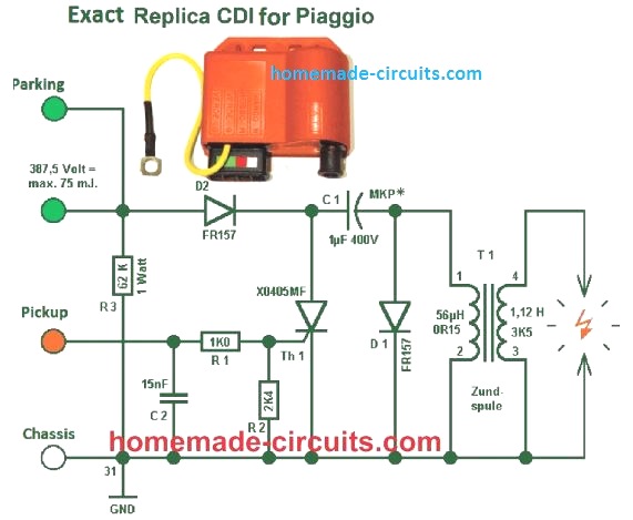
I’m from Brazil.
I have any problems with Vespa 200 CDI (Brazilian model use Ducati System).
The Indian replace are bad quality, and very expensives , because a hight tax in Brazil.
Do you have CDI diagram for this model ?
Look the Chinese and Indian CDI :
Hi Cleuzio, Reputed Indian brands are one of the best, may be you got a duplicate version. Yes, because of tax the good ones can be a lot more expensive in your country.
The CDI version explained in the above article is the universal design which can be used for all 2 standard wheelers
good morning Swagatam congratulations for the work presented – my engine has 2 pistons with 2-stroke operation but does not have a pickup coil trigger – it only has alternator ac current – it is a system used in all simple moped bikes – you can supply the model of the electrical diagram of the CDI? thanks for the help – Alvaro Tolda Lima
Thanks you Alvaro, you can definitely use the above design for your bike, it should work. However you will need a pickup coil triggering for the operations, so you may contact a qualified mechanic to get it installed in your bike too.
ist time on the internet !
i have a problem with a honda 1980 cg125 field bike im trying to fit a cdi to it.
no lights or no battery, just want it to run on a field
its an ac unit. can i use the black wire (1.5vAC) to trigger the cdi unit. the original pointswire
the are other wires on the plug 2v 4v 6v fron the genarator.ac
the cdi kit is a coil reg and cdi and a solanoid which i dont need,
ive tried to takeing the gen wire off the points and just used points earth to try and triggr the cdi ,no luck !
i do hope someone can help me with this problem ,thank you very much for reading this stephen.
The triggering signal must come from a pickup coil, or any arrangement that creates a single 5V or 12V pulse in response to each rotation of the wheel.
Hello Schwagant
Build myself a hydrogen generator from Stangle Meyer without the use of chemicals, only with pure water. For this I need a pulse generator high current low pulse generator which is described by other providers with ultra-short pulse generator. I have a 12V 70 amp alternator in the car. Where can buy a ready-to-install pulse generator or a complete kit with instructions. Please help.
I’m from Germany (Bavaria)
Can’t translate English on the PC
Hi Andreas,
You can very easily build a 12V high current pulse generator using an IC 555 PWM circuit as shown in the following diagram:
Let me know if you have any further questions!
Hi!
Great circuit. Would it be able to run a larger 3.3L 6 cyl tractor gasoline engine?
Thanks!
-RF
Hi, Thank you, yes it can be, the main capacitor will need to be increased to 2uF/400V or maybe 3uF/400V
Hi, in your page there are many ideas for projects, great job congratulations, where can I find a circuit to test the CDI? do you have any diagram to make or what data do I want at the input in the green terminal and in the red terminal? white is a mass. Thanks.
Hi, thanks, please see the video, and replicate the set up exactly as shown in the video, you will be able to test the circuit in this way. See how two transformers are connected back to back to get a low current 220V for testing the CDI
Hi Swagatam
I’m just looking at your CDI design. I’m about to construct it but I have a couple of questions I hope you can answer?
1/ In the first graphical design the cathode of the bt151 goes directly to ground but in the circuit diagram below that image the cathode goes to ground via an in4007 diode. I take it the first diagram in correct and the schematic is wrong? Please advice.
2/ If Ignition timing is to be advanced or retarded, Im guessing the only way to do that would be to set up the motorbike timing to be fully advanced then process a delay through an arduino or similar cpu to retard the ignition timing, dependent on the rpm?
Thanks and regards Steve
Hi Steve, the schematic and the PCB drawing are both exactly the same. In both the designs, the cathode of the SCR goes directly to the ground.
Advance retard can be done by special circuits with the help of the triggeres obtained from the pickup coil
Hi Swagatam, oops I didn’t spot the ground line. I was looking in the wrong place 🙂
Am I right in assuming D1 could be omitted as could R5?
R5 is operating as a part of a voltage divider bringing the voltage at the gate down to 7.69volts but the BT151 will handle the 12volts from the pickup without needing to drop the voltage. Is there a reason why you did that?
If D1 is blocking voltage to ground, couldn’t that be omitted too?
Thanks
Steve
No problem Steve!
I think nothing should be omitted in the circuit since the design is tested professionally in automobiles with perfect results, so I won’t recommend modifying anything in the design. Every part has some relative function and should not be omitted.
Hi Swagatam
I’m just trying to work out how to obtain the 12 volt signal from the pulser coil of a Yamaha DT200LC to input to your CDI unit. I believe from the bikes wiring diagram the pulser coil only has 2 wires so I’m uncertain how to obtain a 12v pulse from it.
I’m guessing it’s a Hall Effect sensor and the 12volts is generated by the pulser coils when the pulse magnet passes the sensor, the sensor not having any power supply and one side of the coil goes to ground? I’m guessing this based on the fact the bike will run without a battery fitted so presumably no power is being sent to the pulser coil.
Do you have any ideas that could help me sort out the issue?
Thanks
Steve
Hi Steve, yes the trigger input to the CDI can be through a Hall effect sensor and magnet assembly on the wheel, however, a Hall effect sensor cannot work withpout an external supply. You will need a 5V external supply from the alternator to feed the hall effect and then direct it to the CDI.
Linear Hall-Effect Sensor – Working and Application Circuit
Thanks Swagatam
Could the 5volt supply for the Hall effect sensor be taken from the 230volt low current AC from the alternator that is used to charge the CDI capacitor? I realise I will need to rectify and regulate the voltage.
I’m just trying to work out how to get the 12v signal from the Hall effect sensor to trigger the SCR 1.
If the bike normally runs without the need of a battery, the supply voltage for the Hall effect sensor must be coming from the alternator, but it comes via the CDI.
Any ideas?
Thanks
Hi Steve, yes you can extract any desired voltage from the alternator using the following capacitive power supply
Hi Swagatam
Thanks for all your help. Can the same voltage from the alternator to run both the capacitive power supply as well as supplying the voltage to the CDI capacitor C4?
Thanks again.
Steve
Hi Steve, yes the 5V will serve as the triggering voltage from the hall effect, and the 220V AC from the alternator can be used for the CDI
Hi Swagatam!
In the circuit of the link below, does diode D3 and D4 have a function to partially recharge the capacitor? I ask this because the primary of the coil generates oscillations after the spark is generated, can it be reused?
Hi Marcelo, sorry I can’t figure out the function of the diodes…
@Marcelo
Sorry, but no such luck.
.
D5 shunts inductive kickback from the ignition coil to ground.
.
D3 ensures that the left side of the 1.5uF cap will never go more than the voltage drop of D3, around 0.7V negative.
.
D4 a zener diode, sets how negative the gate of T2 can go, when the pickup coil goes negative.
.
Poorly designed circuit, or a case of the “money guys” wanting the engineers to cheapen a better design.
.
Hope it helps, but I can’t see any date on the posts (???), or a direct way to reply to a particular post.
.
/Søren
can you please show and explain a circuit diagram for a scooter cdi that has the ability for advancing the ignition sparking for when the engine speeds up
Sorry, I do not have a CDI circuit with an ignition advancing feature
Hi Swagatam
First Let me say I love your site and have bookmarked it.
I have been looking for a long time for a simple CDI set up to go between the set of points, and the existing ignition coils on my positive earth classic motorbike.
Can any of these circuits be redesigned to take positive earth/ frame wiring.Obviously all the Diodeswill need to be turned arround but I’m not confident about the other components,
Please advise.
Best regards Desmond Tutu
Thanks Desmond, glad you liked and bookmarked this site!
I don’t think changing the diode polarity will make the design compatible with a positive earth vehicle. It looks more complex than that, because we have an SCR whose polarity will also matter. Actually I am unable to find an appropriate solution at the moment. If I happen to find anything useful will surely let you know.
Hi Swagatam
I am from Philippines and I have an interest about this topic can I use your diagram as a reference in our research paper to support my argument that there’s an AC CDI in the ignition system of the motorcycle. I ensures that this will be use only for educational purposes.
Please advise.
Best regards John Lloyd
Hi John,
No problems at all. You can feel free to use the concept in your papers.
Hi Swagatam
I have a 1960 vintage CDI that resembles similar DIY products usually marketed by Tandy or Jaycar for the hobby market, except this one has been commercially produced and after 60 years has failed.
Enquiries suggest that it is the capacitor and that the early capacitors failed because they ‘dried out’, is this still a problem.
Geoff P
Hi Geoff,
60 years is a long time, and we can’t expect more from an electronic device.
CDI circuits don’t use an electrolytic capacitor for the capacitive discharge, rather a PPC a metallized PPC is used which do not have electrolyte inside. So “drying out” of the capacitor may not be possible. Nevertheless, wearing out of the capacitor may be possible due to overuse. Another part that can go faulty is the SCR which is subjected to a huge amount of stress during the charge/discharge switching process
Hi, in your cdi circuit, why do you put a diode who is shorting
the negative part of the AC wave from the alternator ?
Hi, it is not my design, it is the original design taken from rickshaw CDI.
Because as stated, it is half wave rectified DC. So it is only rectifying half of the waveform. The voltage is high enough that half wave pulsed DC is sufficient to charge the cap. and we only need a small DC pulse from the trigger coil to fire the SCR. So long as the trigger provides the I(gt) that the gate on the SCR needs (typically only like 0.5-50mA), it will latch the SCR and discharge to the primary of the ignition coil.
Need a cdi design for 650 cc s40 suzuki motorcycle. 2001 single cylinder. Thanks Nick
I think you can try the same CDI circuit explained above. It should work.
Thanks Nick
I do not understand…4 diodes in the picture but 3 in the schematic.
Which one is correct?
Shunt kickback voltage? Diode from cap output to ground.
The PCB layout picture and the schematic diagram, both have 4 diodes.
Dear Swagatam, Im thinking of using this circuit as the electrocution supply for the mosquito killer circuit you did in another link. How can I limit it to only 3500V and 9mA current? Thank you.
Hi Kitt,
In the PCB schematic you can see one terminal labelled as 100 to 200V AC from alternator. You can experiment with this AC voltage and reduce it to 24V AC in order to step down the output voltage from the CDI coil to the desired limits. Just as the AC voltage the current can be also reduced at this terminal.
Thank you vmuch. I assume when you put 200 volts AC, you wil get 20000 volts CDI output. so if its 100 VAC, goes down to 10k volts, and 24VAC goes to 2400 VAC. First there is a way to measure the Voltage using any voltmeter, etc? Or does the CDI have specs printed to show how much is the multiplier to the output? 2ndly, since we decrease the voltage to say 2400-3500V, what space distance would you think the mesh screen should have between each other? Thanks again 🙂
Your assumptions are correct, however I cannot confirm the exact output voltage that you may get using a 200V or a 24V, from the CDI coil.
One way of determining it is to connect 5nos of 1M resistors in series across the CDI output and measure and verify the voltage across these resistors using resistive divider formula.
The distance between the mesh wiers could be around 3 to 5 mm.
I think I have a related article posted in this blog which you can see in the following link:
https://www.homemade-circuits.com/mosquito-killer-circuit/
Thank you again. Got it with the mesh. Regarding the 5nos 1M ohm resistors..so I will have to measure using voltmeter in 1 resistor. So the “20k volts” would be divided through the 5 resistors effectively giving 4000volts each. Can we measure using ordinary voltmeter? Another question is if I intend to use 24VAC up to 110VAC, will the specifications or values of the components in your circuit be changed? and what are they incase I use 110VAC and/or 24VAC? Thank you again 🙂
I don’t think the total voltage can be determined by measuring the voltage across 1 resistor. It looks much more complex than that. So the resistor method might not work. If you have a voltmeter which can measure upto 5000V then you can simply use the meter to measure the output directly. Remember the output will be pulsed, so the meter will show only the average value of the pulsed DC. For example if the input 12V trigger pulse has 50% duty cycle then the voltmeter will show 50% of the actual output voltage from the CDI coil.
The circuit will not need any changes for input AC voltages ranging between 12V and 200V AC.
Ok great! Very clear and well said. Ok. I will make the 110VAC (60hz) as my trigger pulse. anyway, the mosquitoes still will get electrocuted around 10000VAC. Im doing this to replace the High Voltage transformer that I use (very costly due to shipping 🙂 and if damaged, u have to replace cause its hard to rewind. Thanks again Swagatam! More power to you and on what you do! 🙂 Namaste!
Thank you Kitt.,
The trigger pulse should be 12V DC pulse and the AC input can be a 110V AC.
Yes, certainly 10000V should be more than enough to electrocute the mosquitoes
Sorry, forgot to ask. Do I have to put the 680 ohms resistor in between R4 and Trigger as shown in your video? what is its purpose? Thanks.
You can add that resistor for an increased safety for the SCR…the value can any value between 470 ohms and 1K.
Ok Thank you Swagatam! 🙂
You are welcome Kitt.
Dear Mr Swagatam.
I am not an expert in electronics. Need your advice please,
I own a small (Mosa msg chopper) 2 stroke engine welder and I’m having problems getting back the spark.
The thing is that this engine has an AC type of ignition which I’m not used to work on.
I say AC cdi because the engine does not have a battery or any sign of a direct current/wire going to the cdi unit. Please correct me if I’m wrong.
I daily work on mopeds of which most cdi ignition systems are built with charge capacitor or exciter coils and pick up/trigger coils located as two different coils on their own spot under/beside the flywheels.
This Mosa engine has only 2 coils under the flywheel/magnets:
1.The exciter coil or charge capacitor coil which function is to keep the engine sparking/running.
(I came to the understanding that the exciter coil and trigger/pickup coil are
fabricated as 2 functions in one coil)
2.The electromagnet coil which function is for WELDING ONLY. (not important for
spark)
The cdi unit has 4 terminals indicating the wire colors and their functions.
charge capacitor coil (green)pulse/ trigger (red)main coil (blue)ground (black)
The exciter coil or charge capacitor coil has two terminals going to the cdi unit. A red wire and a green wire.
The red wire is for pickup/pulse and the green wire is for the charge capacitor or exciter as shown above.
This is my first experience with this type of ignition of which I experience no pulse/trigger coil internally/externally visible.
The main coil which goes to the spark plug is OK.
I tested it on my moped and gives a nice blue spark.
My goal is to rewind the exciter coil but the engine manual only specifies the resistance for the electromagnet coil (2.9ohms) which is for welding function and not for spark.
There is no info on the exciter coil and it’s resistance.
I dissembled the wire from the exciter coil and opened up the cdi unit which I pretty much damaged some parts of but I was planning to buy a new cdi unit THAT FITS THIS TYPE OF CDI anyway.
The exciter coil is not available in stores so I will need to rewind it.
Please your advice on rewinding the exciter coil and it’s resistance.
If you would like to see some photos of the parts and/or the engine then I can send them to you via email or whatsapp.
mosa.com.au/inventory/manuals/MSG%20CHOPPER.pdf shows the engine manual.
Regards,
Dan
Hi Dan,
Sorry, I have no idea regarding the rewinding process of the exciter coil, because I have never come across practically with these types of systems. I hope someone else in this forum might be able to provide some help.
Hello. I made a CDI according to your scheme but I do not know why my R4 burns. Please help???
The pulse voltage to R4 gate resistor is supposed to come from the pickup coil which has very low current. What is your source for the 12V signal?
If it is from a power supply, decrease the voltage to 5 V or increase the R4 value to any value between 100 ohms and 1K
I use for yamaha YZ 125 1993. Tomorrow I will measure the voltage on the
pickup coil
OK, no problem!! Also you can feel free to increase the resistor value upto 470 ohms.
Hello Sir. I have the same problem. My 12v source is from pulse generator with 20.9 ohms 14.75mH coil. It burns when I reach 4000RPM.
Hello Andrew, the above CDI circuit has been extensively tested and used on Indian motorcycles and auto-rickshaws without any issues. So the CDI components and diagram is absolutely correct.
It can be difficult for me to troubleshoot your issue without checking it practically.
I have a cdi for 2001 650cc savage motorcycle. It will supply a single spark and than quit, till I cycle ignition off and than back on for a single spark repeating each attempt to start. Coil. Plug, igniter and wiring have all been replaced. Any hint or answers would be appreciated. Thanks, new cdis from Suzuki are 700. Dollars . Thanks Nick carper.
The CDI will require a continuous source of pulses from the pickup col to keep the ignition sparks alive and kicking. Is your pickup coil providing the required pulses for this?
thanks for your answers to my inquiry. Yes I have a trigger coil that is working … Suzuki 2011 savage 650 single cylinder.
I have a Husqvarna 285CD chainsaw. It is in very good condition but the CDI ignition has failed. It is now impossible to obtain a new stator plate with all the coils etc. there are only two coils, one for charging the capacitor and the other to supply the HV for the spark. There is no extra coil or sensor to trigger the SCR/thiristor. I wish to find out how the triggering is done and a circuit to match. Both coils I have appear to be ok. The rectification and triggering are encased in a solid block of resin. I would like to remove the resin block and construct a replacement. Any help , circuit diagram, ideas, etc. would be very much appreciated. Johnl
Sorry, I have no idea regarding how the above CDI circuit can be implemented in your application without a pickup coil trigger voltage for the SCR.
Hi Swagatam,
Thank you for your very useful explanation of the CDI circuit. I have a 1978 Johnson two cylinder two stroke outboard and I think there is a fault with the CDI unit. I have taken the unit apart and exposed the circuit board (which unfortunately caused some damage to components removing the protective resin).
I am trying to find out what the components might have been to recreate the circuit with replacement components and wondered if you might be able to help as your circuit looks smaller but similar. If you would be willing to take a look could I send you a photo of my circuit board to see what you think? Thank you in advance for all the useful information
Thank you Tim,
The above explained CDI design is tested on across thousands of two wheelers and auto rickshaws in India, in fact I have manufactured 1000s of these units and sold them in the local market without issues.
So you can replicate the above circuit and use it for your motor bike.
It could be actually very difficult for me to check the image of your CDI and suggest th component values or create a circuit diagram.
Dear all
can you peaple give me a DC CDI Circuit for 200cc motor bike it will be very helpful
Thank you all for informations.
Hello Padmaharsha,
you can build the CDI circuit explained in the above article, it is perfectly suitable for you bike…
Sir, Is there a way to modify or add a timing adjustment to the cdi circuit. auto or manual??? thanks Nick
Hi Nick, sorry, in this basic CDI circuit design, timing adjustment cannot be added.
thank you so much for your circuits and your help. Nick Carper
Sir, question about how to wire the cdi,, wire that goes to the alternator.. my magneto, has 3 wires coming from engine alternator coil, 18 total coils ,with. six,6 coils per wire 2011 suzuki savage 650 motorcycle. they run to a rectifier . How do I connect the single wire coming from cdi to the 3 wire magneto??? hope i made this clear.. thanks for any assistance. Nick in Missouri.
Hi Nick,
As far as I know, you will need to check the voltages from the respective alternator wires with respect to the body ground of your motorcycle. You may have to use an AC voltmeter to check this.
The wire that produces anything above 100V AC can be connected to the CDI 230 V input.
The 12V trigger input from the CDI must be connected with the pickup coil output of your motorcycle.
I think a good qualified motor mechanic or electrician will be able to guide you better regarding the relevant connections.
Thanks for a swift reply. Great job. I Understand, I think I can figure it out. 5 plus. Nick
Glad I could help!
can i use MOSFET irfz44n insted scr by151
No, MOSFET cannot be used in place of SCR.
Hi, have you tried using this circuit with a square wave DC pulse as the trigger? I am using a similar design, although slightly simpler, only a current limiting resistor to the gate pin instead of a divider and slightly higher capacitance on the capacitor, but basic idea still remains. However I ran into a weird issue of it not revving past 1500 rpm.
Hi, It doesn’t matter whether the triggering pulse is a square wave or a sine wave, the SCR will trigger once the gate voltage crosses the 0.7V mark.
You can try the above design and check if it makes any difference.
Cool I just blew out my cdi on moped and I have no income but I got ability and some junk parts I can salvage all I needed was your information to build replacement cdi and get going again. And I noticed your section HHO which I believe has to do with hydrogen if I’m correct I want to make all my power come from hydrogen and the greatest fuel in world only thing I’ve been stifled by is coming up with easy free supply for electrolyte. But your just the help inspiration I needed book marked¡¿¡
Sure, I can help. If you have CDI related questions you can ask them here. For the HHO related questions you can feel free to comment under the following article:
https://www.homemade-circuits.com/how-to-use-hho-fuel-cell-in-automobiles/
Ya know I looked at that circuit and thought it looks to me like it could take reverse 20 volt except cap and I was right but the regulator was bad and I believe it was in need replaced b4 cool ty for simple circuit
helow sir i wish to have a 4pin cdi diagram..can riv to high rpm hopefully
Hi Mark, can you please provide the specifications of the 4 pins, I will try to help!
greetings Swagatam
I made this once but it didn’t work, I think I made a mistake somewhere,I wanted to know if this circuit is CDI, DC or AC?
thanks for sharing
Hi John, did you supply the 100V to 200V high AC voltage and the 12V pulsed voltage to the inputs of the CDI circuit as shown in the diagram?
Both of these voltage simply needs to be pulsed, it doesn’t matter whether they are AC or DC, they should be intermittent and not continuous, that’s all…please let me know.
Hi Swagatam thanks for reply,
When I made it again I saw that it worked very well, I must have been wrong before, it was really great, thanks
Can you share CDI racing or DC circuit?
And instead of bt 151 thyristor, can I use z44 MOSFET or 2n 3055 transistor?
That’s great John, glad it is working now!
For a DC CDI you can refer to the following article:
https://www.homemade-circuits.com/make-this-enhanced-capacitive-discharge/
No, I don’t think the SCR can be replaced with a transistor, SCR looks more suitable for this specific application.
how can I make a simple unit to trigger a cop coil on my motorcycle
kondensaattori sytyksen lisääminen esim boch käjettömäänn sytys järjestelmään? Palkoko maksaa.MSD A6 on kallis voiko vastaavan tehdä halvemmalla.
like to make a circuit CDI discharge system.
discharge will be at 2000VDC , 12 jule power , 2-3 discharges per sec.
Input voltage 220 V /120 V AC,
please comment
Sure, you can try the above CDI circuit, the sparking frequency will depend on the triggering frequency at the “pickup coil” input terminal of the circuit…
HI, I would like to know the diffrents of a 2 stroke AC CDI to a 4 stroke AC CDI engine? I have a Wisconsin s 14 d engine with the 4 pin AC CDI ign., do you have a CDI circuit diagram for this engine? I tryed a 2 stroke 4 pin AC CDI on this engine and had spark but no run. Any help thanks
Yes that’s correct! 2-stroke CDI gives spark every rotation but 4-stroke engine needs spark only every alternate rotation, during compression stroke only. If you put a 2-stroke CDI on a 4-stroke engine then it may give spark at wrong time (like during exhaust stroke), so engine may fire once but not run continuously.
basically both 2-stroke and 4-stroke engines can use AC type CDI units but the timing and trigger pulse requirements are not same. Even if the pinouts look same and spark comes, the engine might not run, just like what happened to you.
Thanks, Ok the trigger palse is what tells the condenser to release the stored energy to the ignition coil. The timming is fixed to fire BTC on both 2 and 4 stroke engines, what is the diffrents in the AC CDI ?
AC and DC CDIs both work in the same way, there job is to discharge a high voltage capacitor to generate a spark. AC CDI uses high voltage AC from the alternator, whereas DC CDI can use 12V from battery and boost it to generate a high voltage pulse using an internal transformer.
Thanks, What I wanted is to know what’s inside the AC CDI box that makes 2 stroke and 4 stroke diffrent? To make a CDI for a Wisconsin engine, would I have to be an wisconsin engineer?
inside AC CDI for 2-stroke and 4-stroke almost all components are same, they have high voltage capacitor, SCR, trigger circuit, etc. What makes them different is mostly how the trigger timing is set up because 2-stroke needs spark every 1 turn, 4-stroke needs spark every 2 turns. Some CDIs are smart and skip every second trigger but most just follow whatever trigger you give. So if you use a 2-stroke CDI on 4-stroke engine then it may give spark on exhaust stroke also (called wasted spark), not harmful but not best. About your Wisconsin engine, you do not need to be a Wisconsin engineer, you just need to check how many magnets on flywheel, where is the pickup coil, what spark timing is needed and then match a CDI to work with that pulse. You can use ready-made CDI or even build one if you know SCR circuits.
Greetings Swagatam
I have two coils on an outboard motor, that needs a CDI unit, because it’s a 2-stroke motor, with 2 sparkplugs. Will this CDI circuit work? Can I connect both the coils to this one circuit?
-Harun
Hi Harun, this CDI is a universal automobile CDI which should work in all types of petrol or diesel engines, provided the trigger pulse input is correctly timed…..
Hi Swagatam
I have built the CDI circuit, and I wanted to know, can you give me some instructions as how to test, with a multimeter, that I have constructed the circuit correctly? Because I’ve tried connecting it to my engine, and nothing happened.
Hi Harun,

You must first test the circuit on your work bench, and then install in your vehicle.
Please do the following set up and confirm the working of the circuit first:
only if you want to trash your engine. if you use te same CDI, your piston cylinders will get fire at the same time, this would most assuredly not run and may even break your crankshaft, there are millions of Artificial Intelligent spider bots spreading disinformation on the internet.
Need data regarding build of CDI circuit. Desired no reverse in primary coil, and need method of shutting off DC SCR. No second scr or triac. There is charging low value inductor only for CDI capacitor of 2uf. How to stop discharge of power supply filter capacitor to add to the 2uf during main large primary coil discharge. Is separate coil inductor and blocking diode needed for shut off?
You can build the CDI exactly as discussed in the above article, nothing needs to be added or removed…it is a thoroughly tested design, it has been tested on 1000s of 2/3 wheeler automobiles
Dear sir;
What is the power limit of the 100, and 56 Ohm resistors respectively?
Thank you
Hi Jason, they both can be 1 watt rated or above…
Hi Swagatam I appreciate your work I’m interested. I will be highly appreciate your advices. Let me have a some time to study. I’m 75+ y. o. Thanks Gentleman
Hi Altaf, no problem at all… wish you all the best with the project…
Hi Swagatam
Could you please help me for driving the deuterium Lamp.
Hi Parveen,
Can you please show the datasheet of the lamp, then I can design the full circuit diagram for you…
Or you can just provide the main specifications of the lamp, that will also do…
Hello Sir.
I have an Aprilia 50cc motorbike, with a Minarelli V1 engine and a Bosch crankshaft, with 2 coils, 6 volts and an alternator. It also has a point + capacitor. There is no HT coil. The alternator is burnt out with 12,000 turns and I can’t find it. They tell me that it is very difficult to modify. Can you help me with any suggestions. Respect!
Hi Luan,
The original 12,000-turn ignition coil is difficult to replicate accurately. The best option is to convert the system to a CDI-based ignition using an external ignition coil and pickup sensor. This will be more reliable and easier to maintain.
Hello Sir.
Thanks for the answer. If I apply your scheme, TCI with three transistors with a point, I think it should definitely work, but I don’t know how it will be powered.
I believe with the excitation coil (alternator) or I need to add a voltage regulator and battery. If so, what current should I calculate?
Thanks in advance.
Thanks Luan,
which 3 transistor circuit are you referring to, I cannot see any 3 BJT circuit in the above article?
Hi , here Hugo from Brasil, how are you.
I have a Kawasaki KX 250 cc 2 stroke year 1988 with no spark.
I measure de peak of the coil in flywhel an mesasure 150 Volts peak. In the trigger coil 2 Volts peak, correct?
I measured too, the resistance and impedance of the coils and are acordgny to especifications of Kawasaki manual.
how can I test the CDI.
I`m Tecnical in electronics and I have a complete Laboratory to test electronic devices.
Thnk you in advance.
Hugo
Hey, you can test your CDI or CDI coil, using the following setup, let me know if you have any confusions:

Hi, I have been looking for a suitable replacement for a CDI box on my 1976 2stroke motocross racer. It has a exciter coil (120v a/c) and a pulser coil. Peak power is at 11,000 rpm. My question is, why not replace the half wave rectifier with a bridge rectifier?
Hi, yes half wave can be replaced with full bridge, but that is not required for simplicity sake…it still works nicely.