In this post I have explained the correct way of understanding and identifying component specifications in a given circuit schematics, even if the details are missing in the document or the schematic.
Schematics without Part Specifications
When a new hobbyist searches for a particular electronic circuit of his choice, the internet provides him with a multitude of schematics to choose from, and the individual ultimately is able to locate the one which may be perfectly suiting his application need.
However, even after having the entire circuit design accessed, very often the hobbyists find themselves confused with the part specification details, since this is one section which seems to be missing in most of the websites, including mine.
This may be frustrating for anybody, but a knowledgeable user will know that there's nothing to be worried about and how to manage efficiently with whatever information may be given with the diagram.
Building a circuit without having all the details of the parts for the circuit is actually not difficult because components specs is not so critical as the connections are supposed to be.
Here we'll try to understand and learn regarding how to perceive or recognize the details of a part in a given circuit diagram even if it's not supplied in the article.
We'll begin with the resistors:
Identifying Resistors:
Resistors are the most primitive, basic, passive electronic components yet one of the most crucial members of the electronic family.
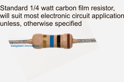
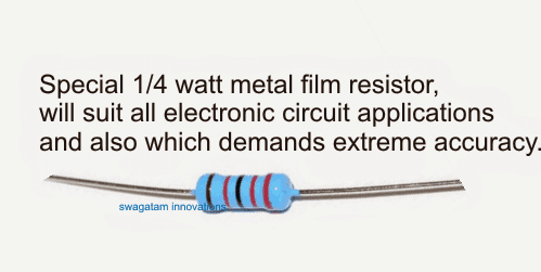
Whenever you come across a particular circuit diagram with no detailed resistor specifications mentioned (only values mentioned), you can certainly assume the resistors to be the default standard ones having the following specs:
Watt = 1/4 watt, typical and standard value
Type: carbon or CFR (carbon film resistor) for non-critical applications, metal or MFR (metal film resistor, 1%) for circuits which may demand extreme accuracy in terms resistance tolerance (not over 1% +/-).
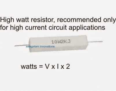
Wire wound type may be opted if the current through the resistor is intended to be above 200 milliamp.
Basically the watt parameter indicates how much current the resistor may safely handle for the given position in the circuit.
Now, after identifying the above specs, sometimes one may seem to be confused with the values too, for example the hobbyist may find the value 750K difficult to find in his locality, but there's nothing to worry about.
Resistor values are never too critical, so for the above example any value between 680K and 810K will mostly do the job, or the user may simply join a couple of odd resistors in series to achieve the same, accurately and efficiently (for example 470k + 270k will yield 740K)
Identifying Capacitors:
Capacitors are normally two types, viz polar and non-polar. The examples of polar capacitors are electrolytic and tantalum, while for the non-polar the range can be quite large.
The non-polar capacitors could be the basic disc ceramic type, electrolytic type, polypropylene type, metallized polyester type.
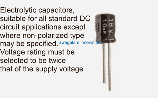
The voltage rating for the capacitors is important and as a rule of thumb, it should be twice that of the supply voltage spec of the circuit. Therefore, if the supply voltage is 12V, the typical voltage spec for the capacitors can be selected to be around 25V, higher than this parameter will never be harmful but is not recommended just because nobody would appreciate an unnecessary increase in the cost and space of the material.
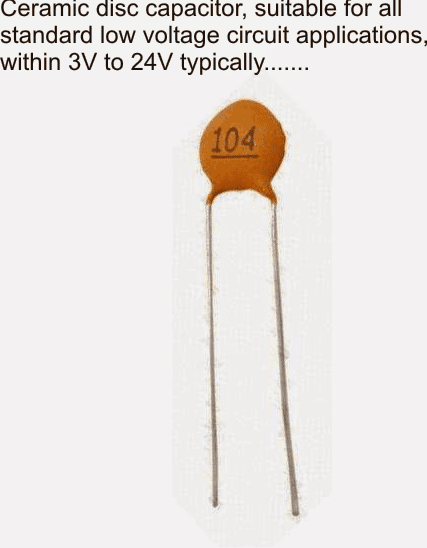
If the diagram has not identified the "type" specifically, one can assume them to be having the following typical specifications:
Non-polar capacitors below 1uF can be assumed to be disc ceramic type of capacitors for most low voltage DC circuits, within 24V range.
For higher voltage circuits, one may need to specify the shopkeeper about the voltage rating of the capacitors, which must be as per the explained data in the above section.
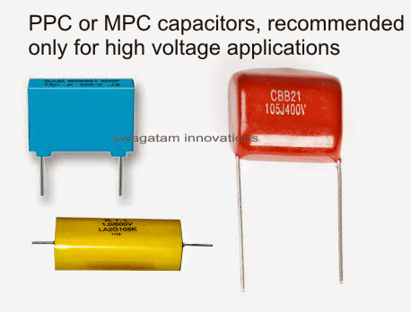
For voltages at the mains level, the capacitor type should be always PPC or MPC, which stand for polypropylene or metallized polyester.
Electrolytic capacitors do not have any specific recommendation, these just need to fixed with the correct polarity and voltage rating to be maintained as per the previous discussion.
In circuits which may demand extreme accuracy in terms of low leakage, for example in timer applications, one may opt for tantalum type of capacitors instead of the electrolytic counterparts which are designed to offer minimum possible leakage and high efficiency.
Identifying Diodes:
Diode specs can be easily identified in any circuit from the given data, since the part number itself will carry all the required info about it.
In a special case if you find it missing, you can assume the specs to be as per the following instructions:
If it's positioned in series with the supply voltage, for normal low current circuits a 1N4007 will do the job, which is rated to handle upto 1amp at 300V.
If the circuit is specified to work with higher currents, then a 1N5408 can be employed which is rated at 300V, 3 amps, a 6A4 may be selected for 5amp circuits....and so on.
For freewheeling applications such as in relays, a 1N4007 or 1N4148 can be used,
for higher current loads such as motors or solenoids the diode may be
appropriately upgraded as described above.
For higher current circuits the device the device simply needs to be upgraded with their amp specs.
If the diode is indicated as 1N4001, 1N4002 etc, simply ignore those and go for the ultimate 1N4007 variant, since its assigned for handling the maximum voltage in the range.
Same may be true for the other diodes too. Always refer to the datasheets of the particular series to learn which one in the range is the most advanced, in terms of voltage specs (not current, because current may be equal for all the diode in the series, for example 1N4001, 2, 3, 4....7 all are rated at 1 amp but with different voltage specs).
If the circuit is a high speed switching type circuit (like SMPS circuit), then the diode could be replaced with a Schottky type diode which are specified to work like fast switching fast recovery diodes. this variant too could be available from lowest to the highest current range, from which the matching device may be selected. Some examples of fast switching diodes are BA159, FR107 etc.
Identifying Transistors:
Transistors are one of the most important parts in an electronic circuit, and this too just like the above components can be customized as per the user's comfort.
Transistors are identified by their numbers which commonly end with a prefix, for example a BC547 may be available as BC547A, BC547B, BC547C etc.
If the circuit is a standard 12V operated one, in that case you can simply overlook the prefixes and just use any "BC547" transistors, however if the voltage spec of the circuit is on the higher side, then the prefix value should be taken into account, because the A,B,C endings indicate the maximum tolerable voltage limit for the device or their breakdown voltage limits. You may want to check out the datasheet of the particular device for identifying its exact voltage rating.
The second parameter which needs to be identified is the ampere (or mA) which can be again traced out from the datasheet of the particular device.
Therefore in an event a BJT number is not clearly specified in a circuit diagram, then the same can be identified by the above explained method, or if the shown number is obsolete and difficult to obtain, any other variant with a matching current and voltage spec can be used instead of the referred one.
The same may be true for mosfet and IGBTs.
Another factor that may become crucial while identifying transistors is their hFe value, however this can be ignored since all low signal BJTs are attributed with high gain or hFe values, so it's automatically taken care of.
So from the above discussion we can conclude that after all it's not so difficult to identify the correct and the safe working part specification for a given circuit, even if a detailed bill of material is not furnished along with it.
If you have more doubts please feel free to ask through the below given comment box
Comments
Hi
I am having a problem in identifying the true code of a transistor
Written on it”TR7N”
I can’t find this code anywhere.
Thanks
Hi, I tried but could not find the datasheet of this device….if you can provide me the operational specification of the circuit, such as the specification of the load connected associated with the transistor in terms of its V and I specs then probabaly I can help you to get the nearest equivalent.
Pls sir help me with inverter circuit diagram that can run ac motor
Sir why a PPC is used parallel with mains supply in some circuits
to sink sudden switch ON current surges
Sir explain in simple words what is an hFe value of a transistor
lower hFe = higher base current required for load activation
higher hFe = lower base current for load activation.
Sir what is a freewheeling application and why is a diode or a capacitor connected parallel with a relay
Mujahid, it's used to short circuit the back emf from the relay coil each time it's switch OFF, this in turn keeps the driver transistor safe from these dangerous currents.
Please sir can u help me on how to connect four 12v 1.5amp transformers in parallel and also help me with a schematic of a 6v 9ah transformerless charger if thats not available post the link to that with transformer not more than 12v…thanks in advance and please reply as soon as possible.
you can connect the input winding of the trafo in parallel but not the output winding, the output winding will need to be terminated separately to different loads
for a transformerless charger you will need to build an SMPS circuit which could be difficult for a newcomer like you….