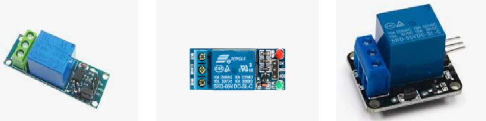
In this post we are talking about this handy little gadget called a 5V single-channel relay module. It is super useful for our microcontroller projects whether we are using Arduino, Raspberry Pi, or even the ESP8266/ESP32. Let us break it down together, what it is, how it works, and how we can connect it.
Understanding the Relay Module
At the heart of this module is a 5-pin 5VDC SPDT relay. This thing is designed to control high-power devices using a low-power signal. It can handle both AC and DC loads as long as we keep them within certain limits.
Relay Ratings (As Printed on the Module)
- 10A @ 250V AC
- 10A @ 125V AC
- 10A @ 30V DC
- 10A @ 28V DC
Basically this means we can safely switch electrical loads up to 10A within these voltage ranges.
Pin Configuration
Now let us look at how this module is set up. It has two main parts:
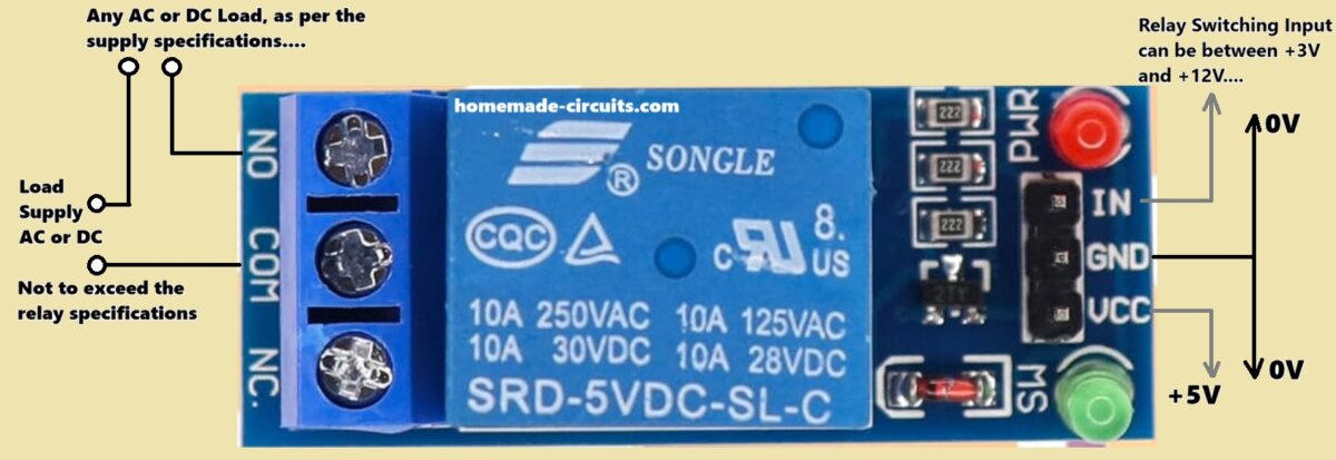
Relay Load Terminals (Left Side - Blue Terminal Block)
Control Signal Pins (Right Side - Pin Header Section)
Load Terminals (High-Voltage Side)
On the left side, we will find three screw terminals:
N/O (Normally Open):
We connect this to one end of our load if we want it to turn ON when the relay gets activated, then we connect it on this contact.
COM (Common): This is the shared connection point for our load circuit.
N/C (Normally Closed):
We hook this up to one end of our load if we want it to stay ON when the relay is not activated, then we hook it up here.
How N/O and N/C Relay Contacts Work
Normally Open (N/O): The load stays OFF until we trigger the relay. When we do trigger it then it connects to COM, completing the circuit.
Normally Closed (N/C): The load stays ON until we trigger the relay. When we trigger it then it disconnects from COM and turns OFF.
Control Pins (Low-Voltage Side)
On the right side, you can see there is a 3-pin header:
- IN: This is where we send a signal to control the relay (it can take between 3V to 12V).
- GND: This connects to common ground for both, the trigger signal and the VCC.
- VCC: This is the power supply for our relay module which must be strictly at 5V.
Working of the Module
So how does this relay module work? It operates through an electromagnetic relay controlled by a low-voltage signal.
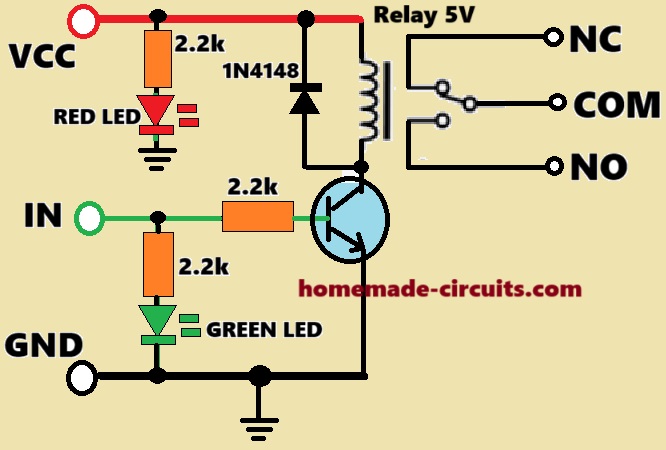
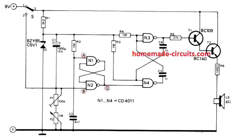
Circuit Diagram
Step-by-Step Functionality
When the input switching signal at IN = LOW (0V or GND) or is turned off, and VCC also turned OFF, then:
The relay does not activate in this situation, meaning relay is switched off or deactivated.
In the above situation, the relay N/C contact stays connected to COM while N/O contact remains open (so if some load is plugged into N/O contact, then the load will be OFF). But if any load is configured with the N/C contacts of the relay, this load will remain ON in this situation, as shown below.

When the input switching signal at IN = LOW (0V or GND) or is turned OFF, but the VCC is turned ON, then:
In this situation the relay continues to remain OFF and in the standby position, waiting for the trigger signal at the IN to be activated through a DC voltage supply between +3V and +12V.
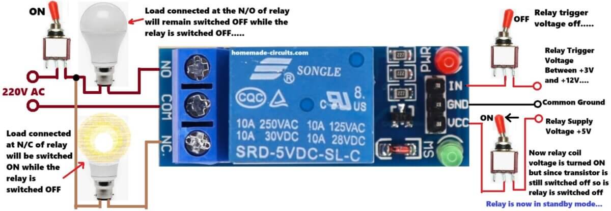
This is because the relay coil is internally controlled through a transistor (BJT) switch, which needs a positive switching or triggering base voltage, which we apply at the IN terminal of the module, see the figure above:
In this situation, any load configured at the N/C contact of the relay continues to remain switched ON, while the N/O contact side load remains turned OFF.
When the input switching signal at IN = HIGH (3V to 12V) or is turned ON, and the VCC is also turned ON, then:
In this situation the relay gets energized, turning on an internal electromagnet.
The internal relay switch or the moving pole shifts, which now connects the N/O contact of the relay to its COM contact, which is the relay pole.
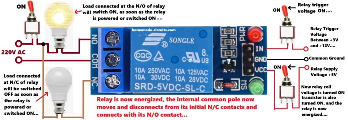
In this situation, any load that may be wired to the N/O contacts of the relay gets powered ON, but now the load which may be configured with the N/C contacts turns OFF.
So basically, the N/O and N/C loads will switch ON/OFF alternately, depending on the input triggering conditions of the relay module.
Internal Components That Help in Operation
Here are some cool internal components that help things run smoothly:
An optocoupler (not included in this module) for keeping things electrically isolated.
A transistor (like a possible S8050, or BC547 NPN) that boosts our control signal for the relay coil to energize.
A diode (the red component near the MS pin) that protects against reverse EMF voltage spikes when the relay coil turns off.
Some SMD resistors (marked with 222 = 2.2kΩ) for limiting current.
Connections with a Microcontroller (Example: Arduino)
Wiring for 5V Microcontrollers (Arduino, ESP8266)
| Relay Module | Arduino Pin |
|---|---|
| VCC | 5V |
| GND | GND |
| IN | Any digital pin (D2, D3, etc.) |
Arduino Code Example
cppCopyEditint relay = 2; // Connect IN to D2

void setup() {
  pinMode(relay, OUTPUT);
}

void loop() {
  digitalWrite(relay, HIGH); // Turns relay ON (load ON if using NO)
  delay(1000);
  digitalWrite(relay, LOW);  // Turns relay OFF
  delay(1000);
}
Using with 3.3V Controllers (like ESP8266 and ESP32)
This module needs 5V for VCC but can accept an IN signal from 3V–12V so it works great with our 3.3V logic directly. For better stability though, it is advisable to use an NPN transistor circuit to adjust the logic level.
Important Notes
Powering the Module
The relay coil needs 5V to work properly. If we are using something that draws a lot of current then it is better to use an external power supply for the relay instead of relying on the +5V input from our microcontroller.
Avoid Overloading
Let us keep in mind that there are limits on how much current the relay contacts can handle—10A max! If we are switching inductive loads like motors or transformers then using a snubber circuit is a good idea (a diode for DC loads and an RC circuit for AC).
Practical Applications
We can use this little module in all sorts of ways:
For home automation, letting us turn appliances ON or OFF from distance.
In industrial control, for managing motors and solenoids.
For security systems to activate alarms or door locks.
In smart IoT projects that control devices via WiFi or Bluetooth.
So this 5V relay module is not just simple but also powerful for switching AC/DC loads using microcontrollers. With careful wiring and attention to its ratings we can safely incorporate it into all sorts of automation and control systems!


Need Help? Please Leave a Comment! We value your input—Kindly keep it relevant to the above topic!