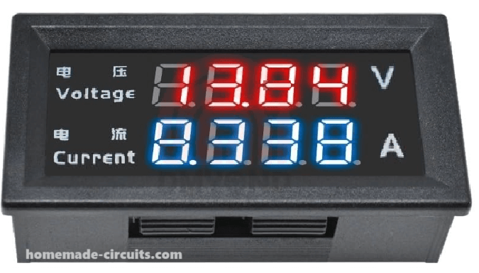
In this post I will be talking about the Chinese M4430 digital ammeter, voltmeter module which is a really neat, compact digital meter that you can mount on a panel. Whats great about it is that it is designed to measure and show us both the DC voltage and the current at the same time.
It comes with a dual LED display which allows to keep an eye on both of these important parameters voltage and current, in real-time making it super convenient for us. We can use this meter for all types of applications whether it is in the automotive systems or keeping tabs on the battery performance or even working on our own DIY electronics projects. It is definitely a versatile tool to have.
Key Features
Dual Measurement Capability
So let us talk about this fantastic feature of this digital meter module. It can measure both DC voltage and current at the same time! We are talking about a voltage range that goes up to 100V and a current capacity of up to 10 Amps.
Compact Design
Now if we take a look at the design we will notice that it is pretty compact. It sports a 0.28-inch 4-digit LED display which is all neatly packed into a panel-mounted enclosure. This means it will not take up too much space while still giving us all the information we need at a glance.
Wide Operating Voltage
When it comes to operating voltage this little device works within a range of DC 4 to 30V. However if we want to get the best performance out of it, then we would recommend sticking to an operating voltage between 5V and 12V. That way we ensure everything runs smoothly!
Reverse Connection Protection
One of the coolest things about this device is its reverse connection protection feature. What does that mean for us? Well it means we do not have to worry about damaging the meter if we accidentally connect it with reverse polarity. That is definitely a relief!
High Refresh Rate
We also get to enjoy a high refresh rate with this meter! It provides us with readings that refresh approximately every 300ms so we can keep track of our measurements in real-time without any annoying delays.
Specifications
Now let us study some of its technical specifications:
Voltage Measuring Range
0.000V to 100.0V DC: This is the range in which we can measure voltage.
Current Measuring Range
0.000A to 10.00A DC: And here is where we can measure current.
Display
0.28-inch 4-digit LED: We have a clear display that shows us our readings.
Product Dimensions
60.00 x 28.60 x 22.00 mm: It is compact enough to fit in various setups.
Mounting Hole Size
57.5 x 26.0 mm: This is the size of the mounting hole for easy installation.
Wiring Configuration
Now let us understand how we can wire this thing up:
Thin Red Wire: This is our positive terminal for the meter's power supply.
Thin Black Wire: This one serves as the negative terminal for the meter's power supply (think of it as our common ground).
Thin Yellow Wire: This is our positive terminal for measuring voltage.
Thick Red Wire: Here is where things get interesting; this is the positive terminal for current measurement and we connect it in series with the load's negative terminal.
Thick Black Wire: Finally this wire is our negative terminal for current measurement which connects directly to the negative terminal of the load's power supply.
How to Wire the Digital Volt/Amp Meter when the Load Supply is Lower than 30V
Well, this scenario is more common in our electronics applications and experiments, because we mostly work with loads whose working voltage is lower than 30V.
In such cases the proposed digital volt/amp meter of the type M4430 or M3430 should be wired in the manner shown below:
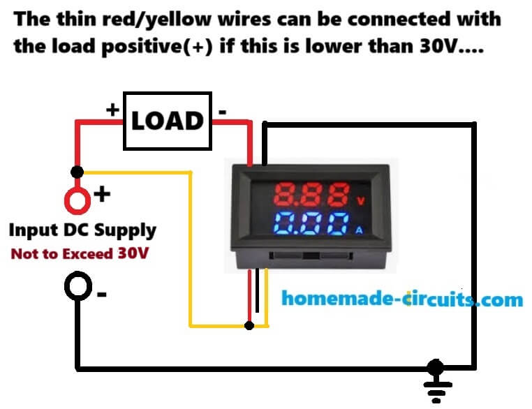
Here you can see that configuration is wired with the following connections:
The positive of the supply input which is lower than 30V is connected with the load positive.
The load negative is connected with the thick red wire of the meter.
The thick black wire of the meter is connected with the supply ground or the negative supply line.
The above wiring configurations simply indicates that the meter current sensing wires (thick red/black wires) must be hooked up in series with the negative line of the load. And this is an essential specification of the meter. This is because the thick black wire which is one of the current sensing wires of the meter must be directly connected with the input supply ground for the meter module to work correctly.
Now the thin yellow wire which detects and monitors the load voltage so that it can be displayed on the meter screen is connected with the load positive, which is also the supply positive input.
The thin red wire of the meter, which serves as the positive supply input for the meter's internal circuitry, requires a supply positive not exceeding +30V. Because our input supply is below 30V, so this thin red positive supply input wire can be directly connected with the existing load positive input supply. And we have exactly done that in our above wiring diagram, by shorting the thin red wire with the yellow wire.
Example Design for Monitoring a 12V Battery charging current and Voltage
The following diagram shows a practical implementation of the above explained configuration in which the working voltage of the application is lower than 30V.
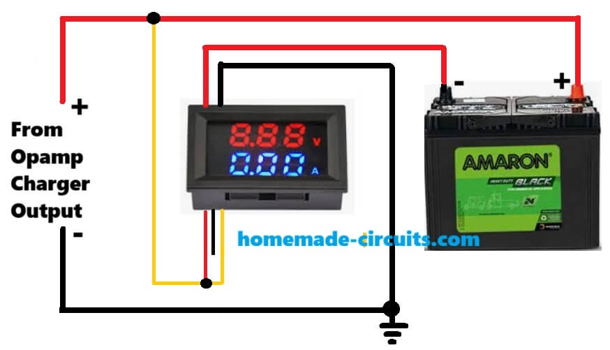
So as explained above you can see that the negative of the battery is wired in series with the current sensing wires of the meter which are the thick red and thick black wires of the meter.
And because the input supply here is 12V which is lower than 30V, the red and the yellow, both the wires are connected with the supply input positive or the load (battery) positive.
How to Wire the Digital Volt/Amp Meter when the Load Supply is Higher than 30V
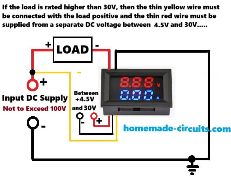
In this example you can see that the input supply is deemed to be above 30V but lower than 100V.
Because the M4430 Digital Voltmeter Ammeter requires a supply voltage between 4 and 30V for its internal circuitry through its thin red and black wires, so the thin red positive wire now cannot be directly connected with the input positive which may be higher than 30V. If you do, the meter will burn.
Therefore, in such cases where the load supply needs to be higher than 30V, the meter thin red/black wires needs to be configured with a separate supply input within the 4V to 30V range, which can be possibly extracted from the existing input load supply through a step down regulator, or it can be a totally separate and isolated power supply source.
Applications
The M4430 Digital Voltmeter Ammeter is not just any ordinary device, it is super versatile! We can use it in a bunch of different scenarios such as:
Automotive Systems: It is perfect for monitoring vehicle battery voltage and current.
Renewable Energy Systems: We can measure output from solar panels or wind turbines with ease.
DIY Electronics Projects: If we are into building custom power supplies or electronic devices then this meter fits right in!
Laboratory Use: It provides real-time measurements in experimental setups making it an essential tool for researchers.


Comments
I have bought one of these modules but… the voltmeter is reading 0.40 volts with zero volts on the load and… it will not measure current if (as in my case) the negative of the load is connected to the negative of the supply voltage.
There are two tiny presets on the board which I assume are for calibration. Which do I adjust to make the voltage read correct?
How do I wire the thick red and black wires to measure current when the negative of the load is connected to the negative of the supply (I’m unable to change that wiring).
Hi, you will have to connect the load exactly as shown in the first top diagram, otherwise the module will not give the intended results.
You will have to disconnect your load’s negative wire and connect it with the thick RED wire of the module and connect the thick black wire of the module with your system’s negative line…
There’s no other workaround using this module.
Thanks for your reply. I have connected correctly. My problem is that the power supply negative is connected to the load negative so that means there is no current flowing through the thick red and black wires. I can not isolate the load negative from the power supply negative. I will have to find another unit that does not try to measure the current the way this module does.
Yes, you will have to find some other module, or make a custom module.
I found a different module. So I will need two. One to measure volts, another to measure current. The current one has 4 wires. Thin red and black connect to a rechargleable battery. Thick red and black connect in the positive supply to the load. See third paragraph which says:
“The easiest and safest way to use the meter is to have no electrical connection between the powering and sensing current. That is, connect something like a 9V battery to the thin power wires and you can put the current sensor in anywhere you want. As long as the circuits are totally separate this will work great….”
Yes, that looks perfect…in that case I think the same configuration can be also tried in the first circuit diagram shown in the above article.
Connect the thin black wire with the load negative (-) supply and then probably the load can be connected in series with the thick black wire, and thick red wire directly connected wit the load (+) supply…
The link I gave in my answer did not show.
It is thepihut dot com / products / panel-current-meter-0-to-9-99a
I think the safest way is to have the 9 volt battery to power the meter so that I can put the current sense part in the positive supply to the load. My problem is that I can not isolate the power supply negative from the load negative.
Sorry, I removed the link because i cannot promote product links on this website.
Yes, the two supply grounds must be common for the digital meter to work….otherwise you can consider using an analogue meter, which will not require any external supply and can be positioned anywhere you want…
Fully understand the reason for removing the link.
I’ve avoided the option of an analogue meter because of the size.
Just a pity I can’t find a similar meter to the one in this web page that has the meter power isolated from the current sensing part.
My only solution seems to be two separate meters, one for volts, one for current that will be battery powered so that the current sense can be placed in the postive lead of the load. It just adds extra complexity with needing a rechargeable battery.
Yes, that sounds perfect…using separate modules for voltage and current sensing. If you are using a separate ammeter, you can derive the power from the load positive and the vehicle ground…
De unde pot sa-l cumpar in Bucuresti Rominia ?
Banggood in China
i dont know if its the same meter or not , but all the wires and unit matches what i got from temu … the one that i got has instructions to use a external shunt to go over the 10A internal limit .. temu also has a 50A/100A shunt
for sale as well.. or you can measure out some 12ga wire and coil it into a shunt ..
It’s not the current range that I have a problem with, it’s the fact that in my equipment the load -ve is directly connected to the power supply -ve, thus shorting out the thick red and black wires that connect to the current sensing link.
Could you also connect the input +Vcc to the negative of the load (assuming there’s enough voltage there)? Would make it a lot easier.
Sorry. That’s not posible. The + and – to the load can not be swapped. It is not a resistor (that would be ok to do that) but an electronic circuit. Applying +Vcc to the load’s -ve would blow it up!
I think I will have to find another way to measure the current – a very low value “shunt resistor” in the positive lead and measure the voltage drop (a few mV) across that.
Yeah, I see. Thanks😊