In this post we will be learning how to interface Nokia 5110 display with arduino microcontroller and how to display some text, we will also be constructing a simple digital clock and finally we will be exploring graphical capabilities of the Nokia 5110 display.
Nokia was the most popular mobile phone brand across the globe before they jump into smartphone market. Nokia was known for manufacturing robust phones and one of the iconic and most robust of all was Nokia 3310.
Nokia brand made lot of noise across social media and meme started floating around internet and most of the meme was about 3310 model, due to its great durability with hard-core users. Some legit source says Nokia phones even saved some people’s life from bullets.
After the reduction in demand for these models in the market there were lot of displays left unused. Now they are refurbished and launched in market for our customized needs.
If want one for hands-on, you no need to create a mini-nuclear explosion around your area to salvage one from your old Nokia phone 🙂 It is commonly available in E-commerce sites.
Illustration of Nokia 5110 display:
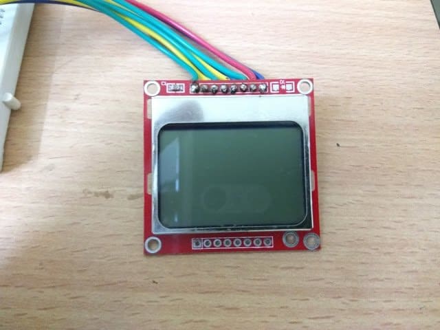
Fun fact: Nokia 5110 display was also used in 3310 model and some more other Nokia phone models too.
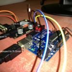
Now let’s see how to connect the display with arduino.
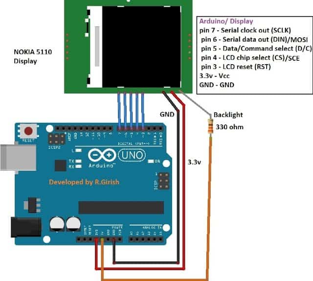
Connect Display with Arduino
The display is monochrome and it has 84x48 pixels which can display text and even graphics.
The display consists of 8 pins: Vcc, GND, reset, chip select (CS), command select, serial data out, Serial clock and backlight.
The display is designed to work at 3.3V and applying 5V will damage the display, so care must be taken while handling it.
The display has backlight functionality which is commonly in white or blue in colour. 5V is given to backlight with 330 ohm current limiting resistor.
Pins 7, 6, 5, 4 and 3 are connected to the digital pins of the display. It is not mandatory to know how the arduino communicates with display in order to use it; we will add appropriate library files to the arduino software which will take care of the communication between arduino and display.
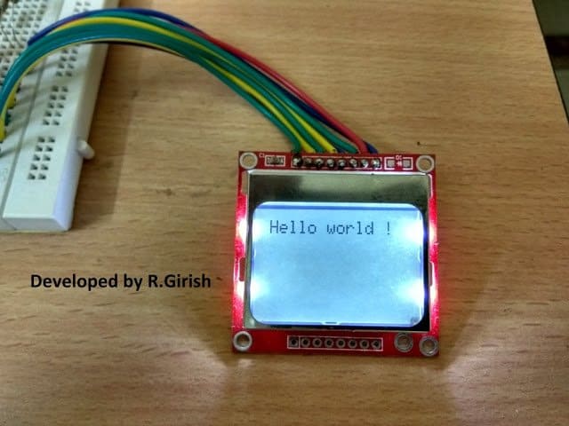
Now let’s display some text.
Displaying Text
Before you upload the code you must download the library files and add to your arduino IDE.
• github.com/adafruit/Adafruit-PCD8544-Nokia-5110-LCD-library
• github.com/adafruit/Adafruit-GFX-Library
Program for Hello world:
//------------ Program Developed by R.Girish ------------//

#include <SPI.h>                 // SPI library (used internally by PCD8544)
#include <Adafruit_GFX.h>        // Core graphics library
#include <Adafruit_PCD8544.h>    // Nokia 5110 / PCD8544 display library

// Display pin configuration (DO NOT CHANGE)
// (SCLK, DIN, DC, CS, RST)
Adafruit_PCD8544 display = Adafruit_PCD8544(7, 6, 5, 4, 3);

void setup()
{
  // Initialize the LCD
  display.begin();

  // Set display contrast (0–100)
  // Adjust if text looks too light or too dark
  display.setContrast(50);

  // Clear any junk data on power-up
  display.clearDisplay();
  display.display();   // Push cleared buffer to LCD
}

void loop()
{
  // Clear display buffer before writing new text
  display.clearDisplay();

  // Set text size (1 = normal size)
  display.setTextSize(1);

  // Set text color (BLACK for normal display)
  display.setTextColor(BLACK);

  // Set cursor position (x, y)
  // Always recommended before printing
  display.setCursor(0, 0);

  // Print text to display buffer
  display.print("Hello world !");

  // Update LCD with buffer contents
  display.display();

  // Small delay to keep text visible
  delay(500);
}

//------------ Program Developed by R.Girish ------------//
If you want to explore more about the coding part, you may take a look at example program, which showcased about graphics, text colour (black/white), test size, text rotation and much more.
Now let’s construct a digital clock.
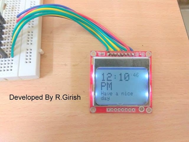
Circuit diagram for Digital clock:
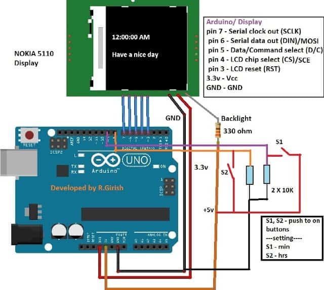
The schematic is same as previous one, only the difference is the two 10K ohm pull-down resistors for setting time are connect to pin #8 and pin # 9; rest of the circuit is self-explanatory.
Program for Digital clock:
//---------------- Program developed by R.Girish ----------------//

#include <SPI.h>
#include <Adafruit_GFX.h>
#include <Adafruit_PCD8544.h>

// LCD pin connections (DO NOT CHANGE – matches circuit)
Adafruit_PCD8544 display = Adafruit_PCD8544(7, 6, 5, 4, 3);

// Time variables
int h = 12;        // Hour (starts at 12)
int m = 0;         // Minute
int s = 0;         // Second

int flag = 0;      // AM/PM tracking counter

// Time set button pins
const int hs = 8;  // Hour set button
const int ms = 9;  // Minute set button

// Button states
int state1;
int state2;

void setup()
{
  // Initialize LCD
  display.begin();
  display.setContrast(50);
  display.clearDisplay();

  // Button inputs
  pinMode(hs, INPUT);
  pinMode(ms, INPUT);
}

void loop()
{
  // Increase seconds every loop (1 second delay below)
  s = s + 1;

  // Clear display buffer
  display.clearDisplay();

  // Display hours and minutes
  display.setTextSize(2);
  display.setCursor(0, 0);
  display.print(h);
  display.print(":");
  display.print(m);

  // Display seconds
  display.setTextSize(1);
  display.print(":");
  display.print(s);

  // Display AM / PM
  display.setTextSize(2);
  display.setCursor(0, 16);

  if (flag < 12)       display.println("AM");
  else                display.println("PM");

  if (flag == 24) flag = 0;

  // Message line
  display.setTextSize(1);
  display.setCursor(0, 32);
  display.print("Have a nice day");

  // Push data to LCD
  display.display();

  // 1 second delay
  delay(1000);

  // Seconds rollover
  if (s == 60)
  {
    s = 0;
    m = m + 1;
  }

  // Minutes rollover
  if (m == 60)
  {
    m = 0;
    h = h + 1;
    flag = flag + 1;
  }

  // Hour rollover (12-hour format)
  if (h == 13)
  {
    h = 1;
  }

  // ----------- Time Setting Section ----------- //

  // Hour set button
  state1 = digitalRead(hs);
  if (state1 == HIGH)
  {
    h = h + 1;
    flag = flag + 1;

    if (h == 13) h = 1;
    if (flag == 24) flag = 0;

    delay(300); // simple debounce
  }

  // Minute set button
  state2 = digitalRead(ms);
  if (state2 == HIGH)
  {
    s = 0;
    m = m + 1;

    if (m == 60) m = 0;

    delay(300); // simple debounce
  }
}

//---------------- Program developed by R.Girish ----------------//
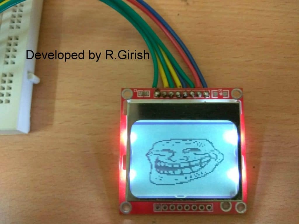
Now, let’s discuss graphical capabilities of the display. The Nokia 5110 display has 84x48 pixels, which can show very limited graphics that too in monochrome. It may not be as capable colour displays in smartphones but, it is very useful if we need to display logos or symbol in your project.
Illustration of graphics using Nokia 5110 display:
Popular troll face:
Dr. A.P.J Abdul Kalam:
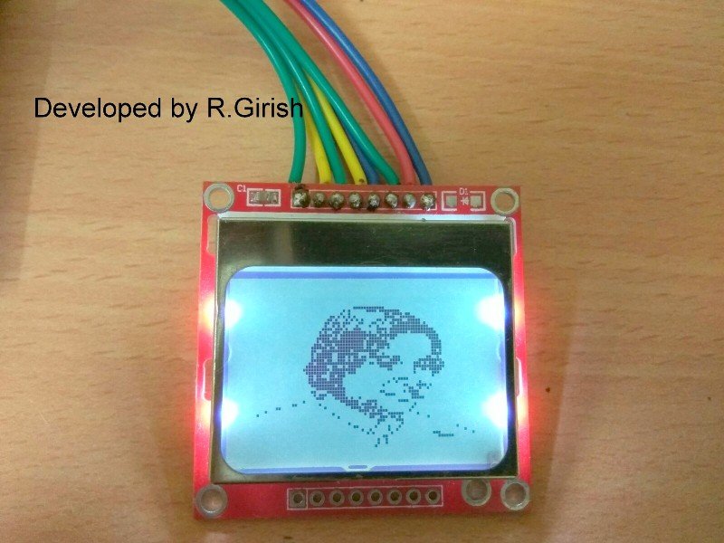
As we can see that using a monochrome display, still we are able display some photos or logos directly from arduino. We no need any kind of external memory such as SD card.
The process of converting a photo into “C” code is subject of another article, where we will be illustrating step by step process.
If you have any queries, please express through the comment section.


Need Help? Please Leave a Comment! We value your input—Kindly keep it relevant to the above topic!