In this article I have explained a simple yet accurate, wide range inductance meter circuit. The design utilizes only transistors as the main active components and a handful of inexpensive passive components.
The proposed Inductance meter circuit can measure inductance or coil values accurately over the given ranges and as a bonus the circuit is also capable of measuring the complementary capacitor values as accurately.
Circuit Operation
The circuit functioning may be understood with the following points:
As we all know that inductors are fundamentally related to generating frequencies or in other words with pulsating or AC supplies.
Therefore for measuring such components we need to force them with their specific functions in order to enable extraction of their hidden characteristics or attributes.
Here the coil in question is forced to oscillate at a given frequency, and since this frequency depends on the L value of the particular inductor becomes measurable through an analogue device such as a moving coil meter after suitably converting the frequency into amplified voltage/current.
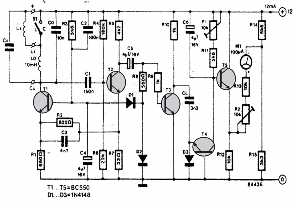
In the shown inductance meter circuit, T1 along Lo, Lx, Co, Cx together forms a Colpitts oscillator type of self oscillating configuration, whose frequency is directly determined by the above L and C components.
Transistor T2 and the associated parts help amplifying the generated pulses at the collector of T1 to reasonable potentials which is fed to the next stage comprising T4/T5 for further processing.
The T4/T5 stage raise the current and integrate the acquired info to appreciable levels so that it becomes readable over the connected uA meter.
Range Selection Option
Here Cx and Co basically provides the range selection option, many good quality caps with precise values may be positioned in the slot, with a provision of selecting the desired one via a rotary switch. This will allow an instant selecting facility of any desired range for enabling wider measurement of any particular inductor.
Conversely, correctly measured inductors/capacitor may be positioned at Co, Lo and Lx for getting an equivalent meter deflections for any unknown capacitor at Cx.
P1 and P2 may be used for monitoring and adjusting the zero position of the meter, it also allows fine tuning of the selected range over the meter.
Meter FSD calibration can be achieved by using the formula:
ni = nm(1 – fr)/(1 – fc)
where ni is the number of divisions measured on the scale, nm = total number of division of the scale, fr = relative frequency, fc = the smallest relative frequency measured.
The current consumption would be around 12mA at 12V while an inductor is being measured.
Circuit Diagram


Comments
Hi, Thanks for you ansver.
After assembly, i got some problems, the multimeter shows one value for various coils.
Used all nominals as in diagram, except transistors, i used 2sc9014 coz they have same voltage and god hfe, as well double checked on errors, all ok.
I set up multimeter on 2mA range (don’t have currently uA, with arrow), then connected 12v bat.
Multimeter shows static value 0.067mA when coil not connected.
when coil is connected, shows 0.021mA and no matter with nominal is, but c5 shows different voltages as well p1 and p2 doesn’t make any changes.
Seems the second part of circuit after c5 works differently, any idea, how to get it working?
Thanks.
Hi, I am really sorry this design is not mine, it was taken from elektor electronics magazine, so troubleshooting could be difficult for me.
you can perhaps try the following, it is a tested design
https://www.homemade-circuits.com/15-v-inductance-meter-circuit/
Can i use c945 transistor instead bc550?
yes you can
Hi Swagatam
I've made a function generator and tried to pass different wave forms through inductors to try and work out the inductances but no positive results.
I want to try and understand the above circuit.
I know how to work out the resonance frequency in the colpitts oscillator(two caps and one inductor in the tank circuit)
How do you include that in the above diagram.
Is it,If you know the value of Co,Cx,Lo then you can work out Lx somehow?
…….If you know the value of Lo,Lx, and Co,then can you work out Cx?
And the deflection on the ammeter how would you change it to farads or henries
Regards Robin
Hi Robin,
waveform will have no effect on inductors r capacitors so it cannot be used as a parameter for determining inductance or capacitance values.
Yes in the above diagram all the mentioned elements are interdependent, basically one must have a standard inductor and capacitor with known values, then these can be used for calibrating the meter. Once the meter gets calibrated with these known values, other unknown values can be proportionately calibrated over the meter dial ….since the reading would be absolutely linear.
Sir,
What is the configuration of the meter? Can I use a PMMC type voltmeter or other?
yes, a moving coil type meter will be required for this design, but a 100uA is the specified rating, a V meter will need to be upgraded or modified appropriately for making it compatible
R8,R11,R14,R1 in rasistains ki valu kiya hi saf dikh nahi raha ro y 10uH my kitny tarns hi y Lo,Lx kiya hi bataiy sir
R8 = 560 ohms
R11 = 5.6k
R14 = 5.6k
R1 = 680 ohms
L0 is a fixed inductor, Lx is the one which needs to be tested.
10uH inductor can be procured readymade from any electronic retailer shop
What software do you use for simulating and verifying these designs? thx.
mind simulation