The circuit presented here monitors the level of the water rising inside a tank and automatically switches OFF the pump motor as soon as the water level reaches the brim of the tank.
The proposed tank water overflow controller circuit is a semi automatic device because it can only sense an overfill and switch OFF the motor but cannot initiate the motor when water supply is introduced.
The user has to switch ON the motor pump manually when water supply becomes available or during pumping out of water from other sources like a bore well or a river.
Water Level Control Using Transistors
The circuit uses only transistors, is very simple and may be understood with the following description:
The CIRCUIT DIAGRAM shows a design involving only transistors and a few other passive components.
Transistors T3 and T4 along with the associated parts forms a simple latch circuit.
When the push button is pressed momentarily, T2 gets forward biased and provides the required biasing to T4 which also instantly conducts.
When T4 conducts, the relay activates and the motor pump is switched ON.
A feedback voltage from the collector of T4 reaching the base of T3 via R4 ensures that T3 remains latched and in a conducting mode even after the push button is released.
Once the water reaches the threshold level of the tank it comes in contact with a pair of terminals positioned at the desired height inside the tank.
The water connects the two terminals and a leakage voltage starts flowing through them which becomes enough for triggering the Darlington pair made up of T1 and T2.
T1/T2 conducts and immediately grounds the feedback signal at the base of T3.
T3 is inhibited from the biasing voltage and the latch breaks switching OFF the relay and the motor.
The circuit remains in this position until the water inside the tank goes below the sense terminals and the push button is initiated yet again.
PLEASE CHECK THIS CIRCUIT FIRST BY CONNECTING A LAMP IN PLACE OF THE MOTOR.
POWER THE CIRCUIT THROUGH A DC 12V SUPPLY.
START BY PRESSING THE SWITCH, THE LAMP SHOULD LIGHT UP.
NOW MANUALLY DIP THE TWO SENSING WIRE TIPS IN WATER, THIS SHOULD INSTANTLY SWITCH OFF THE LAMP AND BRING THE CIRCUIT INTO ITS PREVIOUS POSITION.
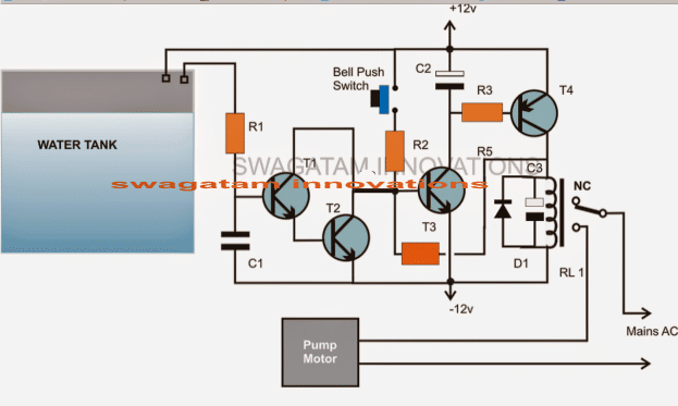
Parts List
R1 = 1K,
R2 = 470K,
R3 = 10K
R4 = 1M (it's situated just below T3)
T1, T2, T3 = BC547,
T4 = BC557
C1 = 0.22uF
C2 = 10uF/25V
C3 = 100uF/25V
D1 = 1N4148,
Relay = 12 volts/SPDT
Push Button = Bell push type


Comments
Sir, With this circuit in place can I eliminate the DOL starter?
Jagan, I did not quite understand what exactly you want to achieve with the above config, is it to sense water and operate the motor or are you interested only to get an electronic replacement for the DOL unit?
also please specify in detail how the DOL works and related with water sensing operations
Sir,
I manually switch on the motor with the help of L&T 3 Phase DOL starter which has a start and stop push buttons. If in case I'm using the above mentioned circuit, please guide me how to go about.
Please guide me through.
Best regards,
Jagadish Kumar S
Jagan, You will have to use a TPTT relay, that's triple pole triple throw relay. This relay will have three sets of contacts, but a single coil. The poles of the relay can be configured with the three wires of the motor and the N/O contacts with the three phases of the AC.
since the relay could be a heavy duty type make sure to replace the BC557 (T4) with a 2N2907 or any other similar 1amp rated transistor
Sir,
I planned to use this circuit for my 3 phase submersible pump which is currently controlled manually using a DOL starter. Kindly let me know how to integrate this with the present setup.
Best regards,
Jagadish Kumar S
Jagan, the set-up detail is shown in the diagram, please provide more regarding what exactly you are looking for?
for 3 phase motor you may have to use a relay having three pairs of contacts for integrating the respective wires
dear bro,
when i put wires to water relay automatically on and when i take off the wire from water relay automatically off. it is working reverse way. what should i do. i'm a hobbyist so pls. instruct me in easy way.
connect another transistor stage with the existing one, remove the relay and connect it with this transistor.
you can take the help of the following example, see how the transistors and the relay are connected,ignore the presets
https://www.homemade-circuits.com/2011/12/self-regulating-lead-acid-battery.html
sir,
please tell me the watt of R1,R2,R3 & R4.
all are 1/4 watt
Thanks for your quick reply sir.
hello sir.
I have tried this circuit several times, but it
can't work. Also tried
the changes specified in a
comment. still no success.
When push button is pressed the relay activate.but the relay can't OFF even if the water level touch the sensing terminals . PLEASE HELP ME…..
for a 1N4007 diode, the cathode will be towards the base of T3…if a zener is used it will be the opposite
hello Naresh,
Connect an LED with a series 1K resistor actoss T1/T2 collector and positive.
When water comes in contact with sensor points this LED should lights up, if not would indicate some fault in the T1/T2 stage.
Additionally, add a 1N4007 diode in series with the resistor joining the collector of T4 and base of T3, this diode could also be replaced with a 3V zener for better response.
Hello Swagatam,
I'm a electronic hobbyist from software field. So I try with the things in the weekend. I saw your blog recently and really admired to test this circuit, and when I went to the market I saw the float switch (www.ebay.in/itm/sensor-float-switch-water-level-controller-3-meter-wire-select-no-nc-/251493496077?pt=lh_defaultdomain_203) there.
Can I connect that to this circuit, orelse will you please suggest me the way to use that, since we don't have to worry about the corrosion & passing currents to water by using this switch.
Thanks for your great works, they are really helpful for the people like us to learn.
Hello tpraveenraj,
usually the disc ceramic capacitors such as this are rated at 50V, and it's not important to mention it while procuring, unless the supply voltage is over 30, 40, 50V
By the way I have published the design requested by you here:
https://www.homemade-circuits.com/2014/04/float-switch-water-level-controller.html
Hello Swagatam,
In the above parts list, it show C1 = 0.22uF, but you didn't indicated voltage. If i'm not wrong voltage of the capacitor is 25 v, right ?
Let me know the voltage of the capacitor.
Thanks,
Praveen
WoW thanks buddys, i'm glad to hear from you.
Waiting for your new circuit & for my new weekend project 😉
Thanks,
Thanks tpraveenraj,
I am unable to make out how the float switch would work, from the image it seems the cylindrical thing around the stick moves up/down with water.
It looks a nice concept and I would want it to explain through a new post, because it cannot be integrated with the above circuit and will need too many modifications.
I'll try to do it soon, please be in touch
Sir, I have a one queary that why there is no connection between R4 and collector of T4…..In which way they will be connected plez clarify me as soon as possible
R4 is connected with the collector of T4, the break indicates that it's not connected with the emitter of T3.
this circuit is not working I tried several times even on solder less board too. when I connect power circuit is always on without pressing on switch despite D2 disconnected. circuit is off only when feedback resistance disconnected. Circuit not off even water level touches probes.
Circuit will work only if you understand it and troubleshoot stage wise.
t2/t3 is a latch which will 100% work. Test and verify it separately, so first make this circuit work by disconnecting D2.
if your circuit is operating even with D2 disconnected when switched ON, it means T3 base is receiving stray disturbance and is switching ON, so attach a capacitor may be a 10uF at its base and ground, this will prevent the latch from operating automatically…check this issue manually until the automatic latching stops.
T1/T2 will surely conduct when its base gets bridged with positive via water.
Replace D2 with a wire short and now check the operation of T1/T2
Hiii
i am Gaurav sheta. how much current withstand this circuit means how much HP motor we used??
It will depend on the relay contact rating which is being used, it can be upgraded to any limits as per requirement.