This simple capacitor tester is capable of testing leaky electrolytic capacitors in the range of 1uf to 450uf. It can test large start and run capacitors as well as 1uf miniature capacitors rated at 10v. Once you understand the timing cycle, you can test down to 0.5uf and up to 650uf.
By Henry Bowman
How to Make this Capacitance Tester
The capacitor leakage tester circuit was made out of some junk parts I had on hand as well as a couple of op-amps and a 555 timer. The test is based on a timed cycle of charge, where two voltage compartors indicate 37% and 63% of charge.
Referring to the schematic, the capacitor is connected to the terminals labeled C. One side is ground and the other side is connected to a rotary selector switch and also to the inputs of two op-amps. The “G” position on the rotary switch is a low resistance ground to discharge capacitors when connected. Large value capacitors should always be discharged before connecting.
Circuit Diagram
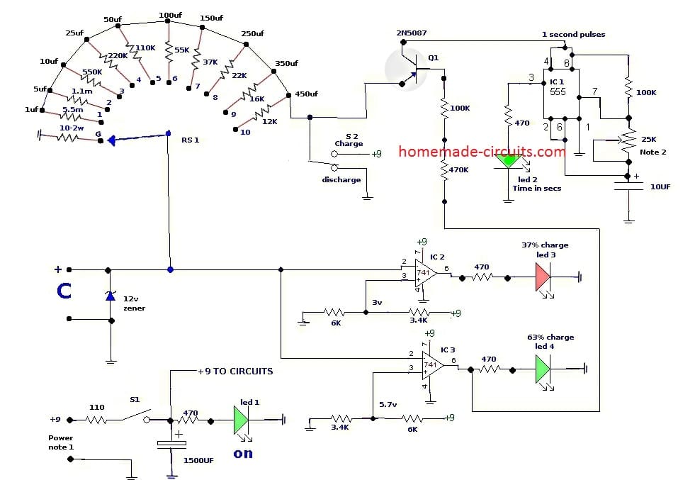
The 12 volt zener is also for voltage protection. If the capacitor is polarity marked, the red dot, or + should be connected to the positive test lead. The selector switch should also be in position “G” when connecting. S2 should be in “discharge” position.
The rotary switch resistor sizes were determine by inverting the formula T=RC, so that R=T/C. Each value of resistor on the rotary switch is selected to provides an approximate time of 5.5 seconds to charge. The actual average charge time takes 4.5 to 6.5 seconds.
Resistor tolerances and slight differences in capacitor values create the difference in the 5.5 second design. The supply voltage needs to be very close to 9 volts. Any lower, or higher voltage will effect the voltage at the resistance dividers at IC 2 and IC 3 input pins 3.
How to Test
The voltage from the ac/dc adapter plug was higher than it's stated 9 volts. I used a 110 ohm dropping resister in series to bring it down to 9v. When the capacitor is connected to the test terminals, the selector switch should be moved from “G' to same value, or nearest value, of capacitor to test.
When S2 is operated to charge, 9 volts is placed on the selector switch resistor through the common wiper to the capacitor to start the capacitor charge. The 9 volts is also placed on the emitter of Q1, a high current gain transistor. Q1 will immediately conduct and power the 555 as Q1's base is at resistive ground potential from IC 3's output pin 6.
The 555 timer lights led 2, once each second, until 63% of charge is reached. The two op-amps are configured as voltage comparators. When 37% (3.3v) of charge is reached, IC2's output goes high, lighting led 3.
When 63% of charge (5.7 volts) is reached, IC 3 goes high, lighting led 4 and also stops Q1 from supplying power to the timer. Operating S2 to discharge provides ground through the same resistor that charged the capacitor.
The 555 does not operate during discharge. Led 4 will go out first indicating that the voltage has fell below 63%, then led 3 will also go out after the voltage has dropped below 37%. Below are the trouble indicators for capacitor tests after verifying that you have selected the proper range and the polarity is correctly connected::
Open capacitor: Will light led 3 and 4 immediately after charge switch is operated. No current flowed through the capacitor, so both comparators will provide high outputs immediately.
Shorted capacitor: led 3 and 4 will never light. Timer light led 2 will flash continually.
High resistance short or change in value: 1. led 3 may light and led 4 stay unlit. 2. both led 3 and 4 may light, but with an charge time greater, or smaller, than designed charge time. Try a known good capacitor and retest.
I had a capacitor labeled 50uf that was taking 12-13 seconds to charge to 63%. I tested it with a digital capacitor tester and it showed an actual value of 123 uf !
If you have a capacitor that falls in the mid range between two capicator values, test on both values. The average between high and low charge intervals should fall within the 4.5-6.5 second range.
A 0.5 uf will have a charge time of 2.5-3 seconds on the 1uf position. Also, testing a 650 uf capacitor on the 450 uf position will provide a charge time of 8-10 seconds. An alternative to the rotary switch would be spst switches for each resistor. Use a digital ohmmeter to verify the resistance of each resistor before installing. The 6K and 3.4K resistors used at the opamp voltage divider networks should be chosen for low tolerances. A voltage of 3 volts and 6 volts on the dividers would be close enough for the charge cycle.
Another Simple Capacitor Tester
The next design is a simple electrolytic capacitor leakage tester circuit. Quite a few leaky capacitors build an internal resistance which deviates in response to temperature and/or voltage changes.
This internal leakage may behave like a variable resistor put in parallel with a timing capacitor.
In incredibly quick time intervals, the result of the leaky capacitor could be nominal, but as the timing interval is lengthened, the leakage current can lead to the timer circuit to alter significantly or perhaps fail completely.
Whatever the case, an unpredictable timing capacitor may convert a flawlessly sound timer circuit into an unreliable piece of rubbish.
How the Circuit Works
Figure below is a schematic diagram of our electrolytic leakage detector. In this circuit, a 2N3906 general-purpose PNP transistor (Q1) is hooked up in a constant current circuit setup whereby a 1-mA charging current is given to the test capacitor.
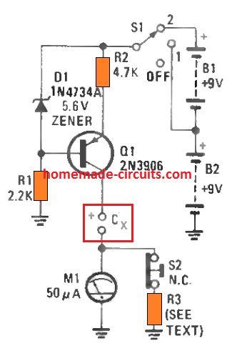
A dual-range metering circuit is employed to display the capacitor's charge and leakage current. A couple of batteries supply power to the circuit.
A 5 V Zener diode (D1) fixes the Q1's base at a constant 5 V potential, ensuring a constant voltage drop around R2 (Q1's emitter resistor) and a constant current on the capacitor under test (shown as Cx).
When set at the S1 position 1, the voltage used on Cx is restricted to around 4 V; having S1 in position 2, the voltage over the capacitor increases to around 12 V. An additional battery could be included in series with B1 and B2 to enhance the charging voltage to approximately 20 V.
With S2 in its normally closed position (as demonstrated), the meter gets wired in parallel with R3 (the meter's shunt resistor), allowing the circuit with a full-scale display of 1 mA. When S2 is depressed (open), the metering range of the circuit is lowered to 50 uA full scale.
Setting Up the Circuit
The circuits in Figs. 2 and 3 demonstrate a couple of ways of choosing the shunt resistor (R3 in Fig. 1) to increase M1's range from its default 50-µA range to 1 mA.
Assuming you have an appropriate voltmeter which can measure 1 V, then you can use the circuit shown in Fig. 2 for determining R3.
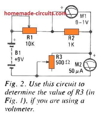
In this procedure, adjust R1 (the 10k potentiometer) to its highest resistance and adjust R3 (the 500-ohm potentiometer) to its lowest magnitude.
Attach a battery as indicated and fine-tune R1 for getting a 1 V reading on M1. Carefully increase the R3 preset value until M2 (the current meter) displays a full scale deflection. Examine only R1 while you alter R3 preset to maintain a 1V reading on M1.
While M1 indicates 1 volt and M2 displays full scale, the potentiometer is established at the right resistance value necessary for R3. You may either work with a potentiometer for the shunt resistor or choose one of equivalent value out of your resistor box. Alternatively, if you have a precision ammeter which can check 1 mA, you cam try the circuit in Fig. 3.
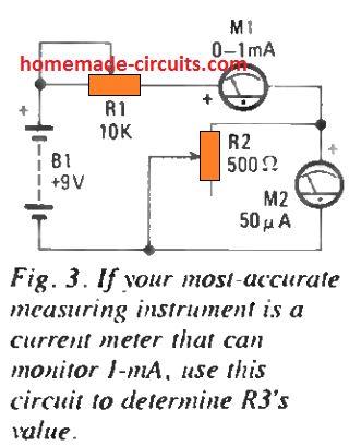
You can implement exactly the same procedures as done for Fig. 2 and fine-tune the R1 for a 1 mA display.
How to Use
To apply the proposed capacitor leakage test circuit, begin with S1 in the off position. Insert the capacitor under test across the terminals, using the correct polarization.
Move S1 to position 1 and you should find the meter (depending on the capacitor value) read full scale for a short interval of time and subsequently fall back to a zero current reading. In case the capacitor is internally shorted or is highly leaking, you may find the meter showing a full scale reading constantly.
In case the meter does come back to zero, try pressing S2 and the meter might not shift upward in the scale for a good capacitor. In the event that the capacitor's voltage rating is over 6 volts, move S1 to position 2 and you should see identical results for a good capacitor.
If the meter displays a rising deflection, the capacitor may not be a good prospect for applying in a timer circuit. Possibly, a capacitor might fail the test yet still be a good device.
If an electrolytic capacitor is not being used or not charged for a long periods of time, this may lead to high leakage current when a voltage is initially applied; but when the voltage stays connected across the capacitor for a reasonable amount of time, the unit may usually get re-energized.
The test circuit could be applied to reestablish a slumbering capacitor by appropriately monitoring the results on the meter M1.
Resistors
(All fixed resistors are 1/4-watt, 5% units.)
R1-2.2k
R2-4.7k
R3—See text
Semiconductors
Q1-2N3904 general-purpose NPN silicon transistor
D1—IN4734A 5.6-volt Zener diode
Miscellaneous
MI- 50 uA meter
B1, B2-9-volt transistor-radio battery
SI-SP3T switch
S2-Normally-closed pushbutton switch
Thank you for the post. It help alot for beginners.
Glad it helped!
Above comment is correct. Capacitor needs to be tested at full rated voltage for 5 minutes (or according to manufacturer’s specs), and amp meter noted at the end of test. I built my own using a Lionel Type Z 24 volt Ac transformer and a voltage multiplier circuit, use 2 vom’s to monitor current and voltage across a resistor loading the cap. Works good.
Adding a variable voltage facility is not difficult at all, it can be easily done through any transistorized variable power supply.
hello i have some doubts about the project:
– why use a potentiometer near the 555?
-why are there two resistors between q1 and ic3, and could you put only one resistor?
-as I understand, can I use the circuit for capacitors above 10v?
-the Rs1 key, can I use a DIP key?
– there is a note on the 9v and the potentiometer, but it is not explained in the text.
pot is for adjusting the output pulse width.
you can use a single resistor at the Q1 base.
You can use capacitor with any voltage rating, voltage rating is not relevant to the testing
RS1 is a rotatory switch, and only rotatory type switch should be used here.
The circuit was submitted by an external author so I am not sure about those notes
thanks for the answers, i will develop this project and for that reason the doubts.
thk’s again take care
good night Sir , Family ok , a question I was looking at the cap leaker tester , do You have the schametic or PCB disign
Hi Ulises, sorry I do not have a PCB design for this circuit at this moment, in future I will try to update it if possible.
The heading of this article is “Use this Capacitor Tester to Find Leaky Capacitors Quickly”. As a Capacitance Leakage Tester it is as USLESS as an ashtray on a motorcycle. The circuit provides no facility to vary a voltage across the capacitor being tested. One MUST be able to vary the voltage across the capacitor to see if the capacitor will operate at its rated voltage. A capacitor rated at 25V that will only carry 10V will cause a cct not to operate as expected.
Thank you for these posts. I am an electronics novice and enthusiast. Thanks