In the proposed BJT pin identifier circuit when the circuit is switched on, two jumpers will have both LEDs ON and the third will have only one LED illuminated.
Investigated, Modified and Written By Abu-Hafss
The E-B-C, NPN/PNP Detector Concept
The jumper with one LED ON is connected to BASE. If it is red LED, the transistor is NPN otherwise, if green, it is PNP.
In the next phase, the switch corresponding to the jumper connected to the BASE is opened. Now, both the LEDs of this jumper will go off. And the only one LED for the other two jumpers will be illuminated.
If transistor was detected NPN, the red LED indicates that the jumper is connected to COLLECTOR and green LED indicates EMITTER. If transistor was detected PNP, the red LED indicates that the jumper is connected to EMITTER and green LED indicates COLLECTOR.
MODIFICATIONS
The LEDs are replaced with opto-couplers. The collectors of the optocouplers are connected with the power supply. A 100k pull-down resistor and a smoothing capacitor are connected with the emitters.
The switches corresponding to J1, J2, and J3 are replaced with reed relays RL1, RL2 andRL3 respectively. All these relays are connected in NC state.
The outputs will be 9V for an illuminated LED and less than 1V for OFF. The outputs of the LEDs corresponding to J1 are R1 for red and G1 for green. Similarly, R2 & G2 corresponds to J2 and R3 & G3 corresponds to J3.
ENHANCEMENT CIRCUIT
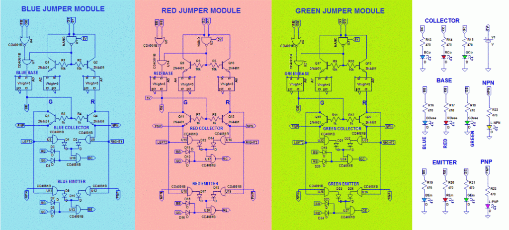
The enhancement circuit has three identical modules each corresponds to jumpers J1, J2 or J3. We assume J1 is BLUE colored; J2 is RED and J3 is GREEN.
And we further assume blue jumper is connected to the base of an NPN transistor (Q-test), red to collector and green to emitter.
CHECKING THE STATUS OF OUTPUTS FROM THE OPTO-COUPLERS
Now, we start with the working of the module corresponding to blue jumper(J1). The opto-couplers’ outputs R1 and G1 are fed into the NAND U1, which checks if both LEDs are illuminated or not.
Presently, the blue jumper is connected to the base of Q-test hence, R1 should be HIGH and G1 should be LOW. Therefore, the output of NAND U1 would be HIGH. (Since R2 & G2 and R3& G3 are LOW, there is no activity in the other two modules).
BASE DETECTION
The inputs to NOR U4 are coming from the other two modules, which check if the base has already been detected or not. We will discuss this issue shortly.
Since the base is not yet detected, both the inputs will be LOW and hence the output will be HIGH. The HIGH output of NAND U1 and HIGH output of NOR U4 goes into the AND U7.This AND performs as base detector.
Presently, the output from NAND U1tells that only one LED is ON and the output from NOR tells that the base has not been detected so output of AND U7 goes HIGH.
This high output is passed thru a latch so that if the output of AND U7 is changed at some later stage, the HIGH state is not disturbed.
This high output is connected thru a resistor to a blue LED designated for BASE. This high output is also send to the red and green modules, to inform them that the base has been detected.
NPN/PNP DETECTION
Now, we come back to the NAND U1, the high output switches on the NPN transistors Q1 and Q2 both acting as emitter follower.
The R1 output is passed thru Q2 and G1 thru Q1. The outputs from both emitters are passed thru latches to preserve the state. Presently, R1 is HIGH hence; the right rail RIGHT1 is powered ON.
The HIGH output from the BASE detecting section also activates transistors Q3 & Q4. Since the RIGHT1 is powered ON, the emitter of Q4 goes HIGH and Q3 emitter remains LOW.
The HIGH state of Q4 indicates that Q-test is NPN. This output is connected thru a resistor to a Yellow LED designated to indicate NPN. (Similarly, if the left rail LEFT1 is powered ON; the emitter of Q3 would be HIGH which means that Q-test is PNP and the output is connected thru a resistor to a Pink LED designated to indicate PNP).
The information about the transistor type is also sent to the other modules thru the nodes labeled ‘NPN’ and ‘PNP’.
SWITCHING TO NEXT PHASE
Both RIGHT1 & LEFT1 are connected thru diodes to the coil of the reed relay RL1 so that either rail can energize the coil of the reed relay. When RL1 is ON, the contacts get disconnected and hence the both the optocouplers gets off and the outputs R1 and G1 go LOW.
However, this change will not affect this module because we have already locked the information therefore; the Yellow NPN LED and the Blue BASE LED will remain illuminated.
On the other hand, as soon as the reed relay’s contacts get disconnected the output of the opto-couplers of the other two modules change their state i.e. one opto-coupler per module will be active.
Now, we focus the red jumper module. Since, the red jumper is connected to the collector, the output of opto-coupler R2 should be HIGH and G2 should be LOW.
The high and low inputs to NAND U2 results HIGH output. The NOR U5; will have HIGH input from the Blue jumper module because it has already detected the Base.
The input from the Green jumper module will be LOW. Hence, the output of the NOR will be LOW. This LOW output of NOR and HIGH output of the NAND U2 goes into the ANDU7, whose output will be LOW.
COLLECTOR DETECTION
The HIGH output of NAND U2 also switches on Q9 and Q10. Their outputs from their respective emitters are passed thru respective latches.
Presently, R2 is HIGH hence the right rail RIGHT2 is powered on. The transistors Q11 & Q12 remain off because the output of the red base detecting section is LOW. The three AND s in the center of each module make up the collector detection section.
The right AND checks if NPN and the red opto-coupler of the jumper is HIGH. The left AND checks if PNP and the green optocoupler of the jumper is HIGH. The outputs of both the AND s goes into a third AND thru their respective diodes.
The third further checks if the other two modules have already detected the base. Presently, R2 is HIGH and the ‘NPN’ node HIGH so the output of right AND U16 goes HIGH.
The Blue Base has already been detected, so now both inputs to AND U17 are HIGH hence; the output goes HIGH. This output is connected thru a resistor to Red LED, designated to indicate Collector.
EMITTER DETECTION
The emitter detecting section works the same way as the collector detecting section except the ‘NPN’ & ‘PNP’ nodes which are connected the other way round.
The three AND s at the bottom of each module make up the emitter detection section. The right AND checks if PNP and the red optocoupler of the jumper is HIGH.
The left AND checks if NPN and the green opto-coupler of the jumper is HIGH. The outputs of both the AND s goes into the third AND thru their respective diodes.
The third further checks if the other two modules have already detected the Base. In the Green jumper module, the HIGH G3 from opto-coupler powers on the left rail LEFT3 and the ‘NPN’ node is HIGH so the output of left AND U25 goes HIGH.
The Blue Base has already been detected, so now both inputs to AND U27 are HIGH hence; the output goes HIGH.
This output is connected thru a resistor to Green LED, designated to indicate Emitter.
After collector/emitter detection, even the corresponding reed relays are energized and their contacts get disconnected, no affect will happen because all the results are locked thru their respective latches.

ORIGINAL CIRCUIT The detailed description of the original circuit can be found at https://www.redcircuits(dot)com/Page83.htm


Comments
Sir. Can u design a circuit to check MOSFETs exactly working or not.while I found. MOSFETs burned in an inverter circuit..normally I change all the. MOSFETs together.I have no idea to find. The faulty ones. If u put any led or buzzer indications to show faulty ones in circuit
May be helpful.
Moonlite, I already have one post in this blog, I have tried to explain the procedures as per my practical experience using a digital multimeter, …….using led indicators could be difficult:
https://www.homemade-circuits.com/2012/04/how-to-check-mosfet-using-digital.html