The following article explaining a dual battery changeover relay circuit was requested by Mr.Raja so that it could become possible to switch between his old and new inverter batteries automatically, eliminating manual interventions. Let's read it in details.
Technical Specifications
"I bought a new 12v 110 Ah lead acid battery for the dc home lighting system. I had another 12v 110ah battery which is about 8year old. ( which is connected earlier in the same lighting system in my house itself) . But the old one has approximately 25ah capacity as i calculated. But it is not sufficient to glow light for about 5 hours of night.(i.e. From 6pm to 11pm) So i want to use old and new Battery. But i can't join them in parallel, as old one may takes charge from new battery, which decrease the life of new one (as i think) Therefore at present i am using a'Two-way' switch to switch on and off between old and new battery. Whenever lighting system controller shows red light, i.e. At about 11.5v, i manually operate the two way switch to switch on the new battery. Now , please give me the circuit to switch on and off between two batteries in such a way that, initially lighting system operates with old bty and as the voltage of old bty decreases (below 11.5v) then only switch on to new one.. Thanking you"
The Design
The designed idea of the proposed dual battery changeover circuit or rather old to new battery changeover circuit may be understood with the following points:
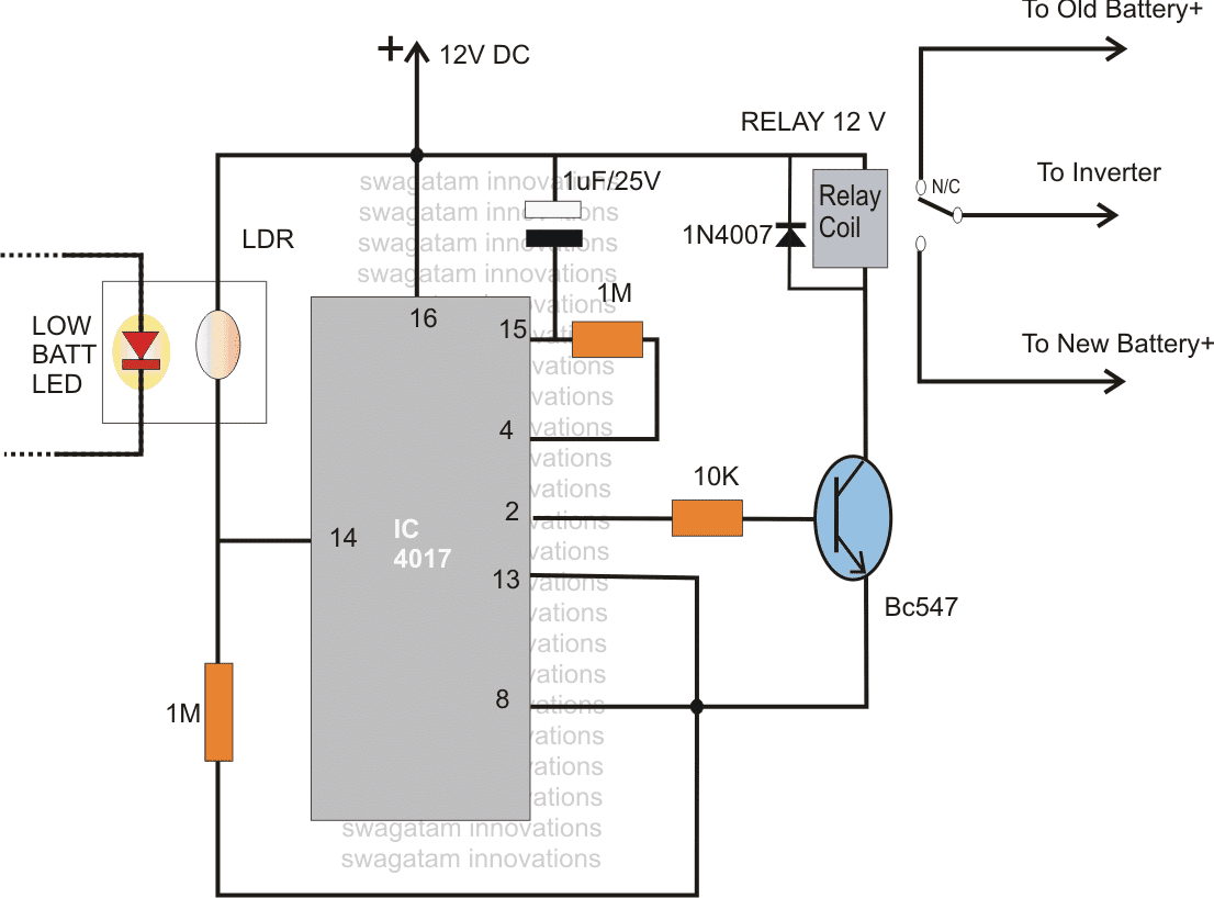
Referring to the circuit diagram we see a IC 4017 which functions as a sequence toggler or switcher.
The IC will shift its output from pin#3 to pin#2 and then to pin#4 in response to every positive pulse at its input pin#14.
pin#4 of the IC has been connected to the reset pin#15 of the IC, means the moment the logic sequence reaches pin#4, the sequence gets reset back to pin#3 so that the cycle can repeat.
Here the input pulse is derived from the low battery warning indicator from the existing inverter system.
The LED light from the low battery warning has been integrated to an LDR using a light proof tubing.
Initially when the power is switched ON, the 1uF capacitor resets the IC so that the logic sequence initiates from pin#3.
The relay at this point remains connected with its N/C pole connecting the old battery positive with the inverter.
The inverter starts operating, draining the old battery
On reaching the low battery threshold, the inverter low battery LED illuminates which instantly lowers the enclosed LDR resistance supplying a positive pulse to the pin#14 of the IC.
The IC responds shifting the logic sequence from pin#3 to pin#2.
Since pin#2 of the IC is connected to the relay driver transistor, the relay immediately activates, switching the new battery into action through its N/O contacts.
The new battery being fully charged toggles OFF the low battery indicator light, the IC goes into a standby position holding the situation intact.... until, the new battery also reaches a low-battery condition switching ON the LED and resetting the IC into its initial position.
The cycle then repeats producing the required automatic dual battery changeover actions.




Questions & Answers
Hi Swagatam,
Nice article. I am having the exact situation as explained above by Mr. Raja. I am trying this idea using MC. When voltage drops to 11.0v on load, i want to switch to new battery. my question is 1. What current rating of relay do i need to use? is it the sugar cube relay[ 7amp] or more?
2. Do i need to connect the -ve of both relays together?
3. Instead of relay can i use mosfet?( for efficiency and more battery time).
4. if yes, which one? I am planning to connect the MC and switching ckt directly to battery terminal for powering the system, which may drain the battery eventually over a period of time.
5. Like wise, i think i can use the same logic to charge the old battery first and next new one. So at what level should i stop charging the old battery before switching over to new one?
6. Or how long should i wait (after reaching battery voltage 13.6v) before switching to next battery?
Kindly help me in this. Awaiting your replay.
Regards,
Sham.
Thank you Sham,
Are your questions with reference to the above circuit? because I cannot see two relays in the diagram.
Relay contact rating (amps) will need to be selected as per the battery AH rating, it can be same as the AH value of the battery.
The battery charging can be stopped and toggled once it reaches the 14.3v mark.
according to me the relay option is better and much safer than mosfets
Hi Swagatam,
I tried the ckt with 7 amps relay. But as the load increased, inverter shutdown. Looks like 7 amps was not sufficient to power the inverter. It was before reading your reply.
My UPS, iam using it as inverter since iam not charging battery through Mains, is 600VA capacity.
1. So to power this system my relay should be 600/12 = 50 or 60 amps right?
2. Or as you said i have a battery of 125 ah, is it 125 ah relay? if yes, Then i think it will be expensive switching..
Hi Sham,
125 AH would be the maximum safe limit, which would ensure that even if the battery was discharged at the full AH rate, the relay would still hopefully not burn or fuse.
However if you intend to use the battery at a normal 30 to 40amp rate in that case a 60 amp relay would be fine.
Pls i tried this circuit out and notin happens my 4017 was jss static on output of pin3 pls i nid reply quick
the LED needs to illuminate sharply or suddenly, if it illuminates slowly then the circuit might fail to respond
Sir what is it's applications..
Dear Swagatam,
I enjoy and follow your well explained circuits which opens my brainstorming data bits.
I have 2x24v dc battery banks which I use to alternate my hybrid inverter supply when I experience prolonged power outages. I manually changeover when a low alarm sounds (24.5vdc) to either bank depending on the last bank discharged. This manual changeover affords me a bump-less power transfer thus you do not see any dips in power. The low battery gets charged immediately .I need help to design a circuit using dc/dc SSRs (SSR-40DD FOTEK) for the changeover switch achieving the same or better and avoiding damage to the SSRs. The max load will be less than 30amps.
Best Regards
Washington David Masunga
Harare . Zimbabwe
Thanks Washington, appreciate your thoughts,
Here’s one SSR concept which perhaps you can try for your mentioned application
https://www.homemade-circuits.com/12v-dc-solid-state-relay-ssr-100-amps/
let me know if it seems suitable..
Thanks Swag
I greatly appreciate your quick response.I shall try the circuit during the week and send you feedback.
Regards
Washington
Thanks Washington, please keep up the good work…
Hi swagatam,
Pls help me need automatic change over switch cutoff after full charging for 60v 24ah dual lithium battery pls share circuit diagram.
Hi Suman,
you can try the last circuit from the following article:
https://www.homemade-circuits.com/automatic-dual-battery-charger-with/
But the above is only the changeover section, for the charger you can refer to the following article:
https://www.homemade-circuits.com/simplest-safest-li-ion-battery-charger/
I need a mofset that switches every 8 hours between 4 batteries
Hi… Thanks for the info…. I have two 12v batteries say A and B to power a led lamp.. How do I build a circuit to cut off and isolate battery A it is low and connect battery B while is automatically charging?
You can try the following concept:
https://www.homemade-circuits.com/automatic-dual-battery-charger-with/
i am doing a project to use wind turbines as chargers for electrical bikes/cars and also for homes with a two-way switch. Actually, my ideal project is using wind turbines to charge batteries while driving and the is full we can switch the battery with the two-way switch to use other battery who is already placed there and if we don’t need any charge to batteries wee can turn off wind turbines. Is it possible practically??? Can you help me in this..
The concept cannot be feasible. If you use windmill on bike, it will create a lot of drag and consume extra battery power from the vehicle, more than the generated electricity from the windmill.
Hi, I want an automatic changeover switch, which swithes automatically to inverter when there is no national grid. A 220-230v input and 50/60 hertz frequency and about 30amps output.
Thanks sir
Please search “changeover” in the search box, you will able to find the exact circuit you are looking for.
Dear swagatam,
I am Donald. I read the request letter by Mr. Raja and the suggestion you gave is great. Please Sir, I need a circuit that will automatically connect the older Battery to auto cutoff charger while the new one takes over.
Thanking you Sir
Thank you Donald,
you can probably try the last circuit from the following article:
https://www.homemade-circuits.com/automatic-dual-battery-charger-with/
Hello Swagatam, if I have one solar panel 12v 200w, 2 batteries 12v 100ah each and a 24v inverter. Now is there any way u can design a circuit such that while it’s charging then the battery combines in parallel and whn it reaches the full charging threshold it disconnects and form a series connection?????????????
Hi Morris,
That looks difficult. To implement this we may have to configure a few relays so that they join the battery terminals in series and parallel alternately, which is not easy.
Can’t figure it out right now.
Hi Mr Swagatam, I need a change over circuit diagram, I want to switch two batteries such that when battery one is below 11.5v, then battery two switches on automatically without interupting the system.I want it for my inverter project.Thank you in advance.
Hi Majaha,
You can try the following design:
https://www.homemade-circuits.com/wp-content/uploads/2024/05/Dual-battery-charger-circuit-using-a-single-opamp.jpg
More details are provided in the following article:
https://www.homemade-circuits.com/automatic-dual-battery-charger-with/