In this article I will comprehensively explain about the early point contact diodes, and their modern versions which are Germanium diodes.
Here I have explained the following facts:
- Brief history of point contact diodes
- Construction of point contact diodes and modern Germanium diodes
- Advantages of point contact diodes or Germanium diodes
- Applications of Germanium Diodes
Brief History of Point Contact Diodes
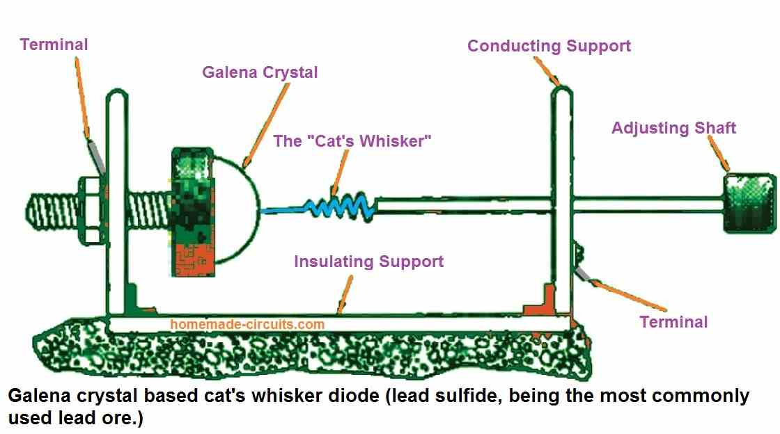
The point-contact diode is the oldest type of diode invented. It was extremely basic and built on a crystal of a material belonging to a semiconductor, such as galena, zincite, or carborundum. The diode was first utilized as a cheap and efficient way to detect radio waves because it had a "cat's whisker."
Karl Ferdinand Braun first demonstrated the "asymmetric conduction" of electrical current, between crystal and metal in a point contact diode in 1874.
In 1894, Jagadish Bose conducted the first microwave research using crystals as radio wave detectors. The first crystal detector was invented by Bose in 1901.
G. W. Pickard was primarily responsible for converting the crystal detector into a useful radio device. He started researching detector elements in 1902 and discovered thousands of compounds which could be utilized to make rectifying junctions.
The underlying physical properties of these early point contact semiconductor junctions were not known at the time they were employed. Further study into them in the 1930s and 1940s resulted in the creation of contemporary semiconductor devices.
Construction of Point Contact Diode
As seen in the figure below, a cat's whisker-like tiny wire was used to contact the crystal. This was preferably one made out of gold to prevent oxidation.
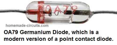
Subsequently, other types of detectors emerged, such as costly germanium diodes and ultimately costly detector tubes.
This led to the widespread implementation of point-contact cat's whisker in broadcast wireless radios during the World War I.
When compared to modern semiconductors, the cat's whisker detector set or crystal set was nowhere near accurate. The "whisker" had to be manually placed on the crystal and fixed in a particular position. However, within a few hours of operation, its effectiveness would decline and a new position needed to be determined.
Although it had many drawbacks, the whisker and crystal was the first semiconductor employed in wireless radios. In those early years of wireless, most hobbyists could afford this, the point-contact diodes functioned rather well, but nobody understood how it operated.
Germanium Diodes (Modern Point Contact Diodes)
Point-contact diodes are much more efficient and reliable nowadays. As illustrated in the figure below, they are made from a chip of N-type germanium on which a fine tungsten or gold wire (replacing the whisker) is inserted.
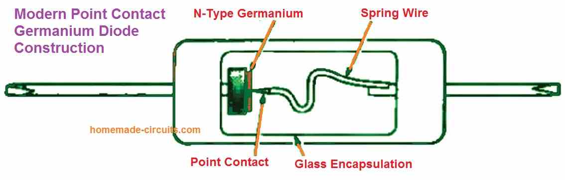
The wire causes some metal to migrate into the semiconductor where it contacts the germanium. This serves as an impurity, forming a tiny P-type region and establishing the PN junction.
Due to the PN junction's tiny size, it is unable to tolerate high current levels. The highest would be typically a few milliamps. The reverse current of the point-contact diode is larger than that of a typical silicon diode. This is an additional property of the device.
Typically this value may range from five to ten microamps. The point-contact diode's reverse voltage tolerance is also lower than that of several other silicon diodes.
The maximum reverse voltage that the device can tolerate, is often defined as the peak inverse voltage (PIV). A typical reverse voltage value for one of these point-contact diodes is roughly 70 volts.
Advantages
The germanium diode, also known as a point-contact diode, appears basic in many ways but has a few advantages. The first advantage is that it is simple to produce.
A point-contact diode does not require diffusion or epitaxial growth techniques, which are normally needed to produce a more traditional PN junction.
The manufacturers could easily separate parts of N-type germanium, position them, and connect a wire to them at the ideal rectification junction. This is why, in the initial periods of semiconductor technology, these diodes were extensively used.
The ease of use of the point-contact diode is its additional advantage. The junction has an extremely low capacitance because of its tiny size.
Even while common ordinary silicon diodes like the 1N914 and 1N916 only have values of a few picofarads, point-contact diodes have even lower values. This property makes them highly suitable for radio-frequency applications.
Last but not least, the germanium used to manufacture the point contact diode results in a minimal forward voltage drop, which makes it perfect for use as a detector. Therefore, the diode requires a significantly lower voltage to conduct.
In contrast to a silicon diode, which requires 0.6 volts to switch ON, the typical forward voltage of a germanium diode is hardly 0.2 volts.
Applications
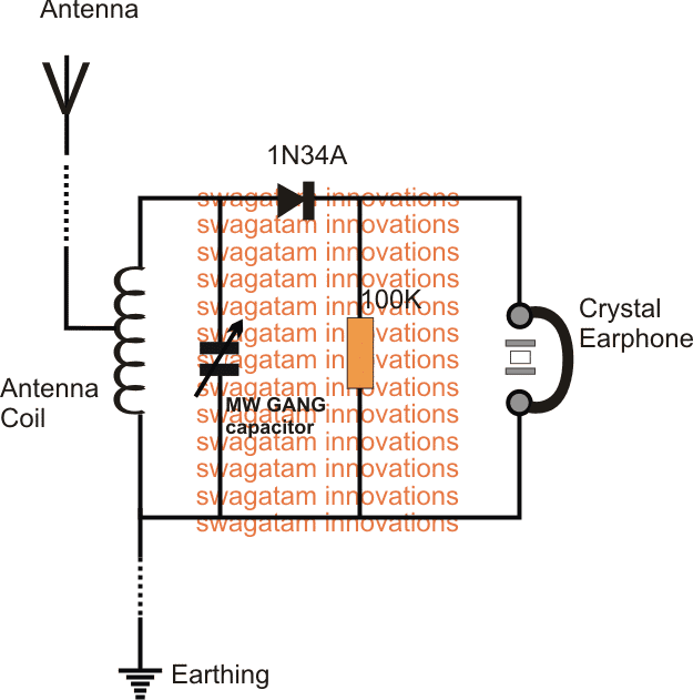
If you are a hobbyist and like to build tiny radio sets then you may find the best application of a point contact diode in a crystal set.
A most basic form of radio receiver that was widely used in the early days of radio is known as a crystal radio receiver. It is also commonly known as a crystal set.
The most fascinating thing about this radio is that it does not require external power to operate. It actually makes audio signal using the power of the radio signal that is received through its antenna.
It gets its name from its most significant component, a crystal detector (point contact diode), which was initially manufactured from a crystalline material like galena.
A simple crystal radio using a point contact germanium diode 1N34 can be seen in the following diagram.
For the complete article and description of the circuit you can refer to the following post:


Need Help? Please Leave a Comment! We value your input—Kindly keep it relevant to the above topic!