In this post I have explained how to build a simple yet foolproof infrared based remote control, which can be used for locking and unlocking any vehicle door through a personal remote handset.
The remote controlled vehicle door lock is foolproof since it works only with a specific IR frequency range, and will not respond to a different frequency to the one set in the circuit.
The most widely used frequency range intended for remote-control purposes is in the 900 nanometer spectrum, generally known as the infrared spectrum of the light range. This is the spot in which the most of the InfraRed (IR) LED's and phototransistors generate the maximum output and sensitivity.
The most basic IR remote control system is one that works with a switched (on/off) IR light supply for a transmitter and a photo-sensitive detector device having a switchable output for the receiver.
This kind of remote-control systems functions only with a condition that the receiver does not get subjected to some other IR light source. Because the receiver is unable to differentiate between a day light IR radiation or any other high intensity source, from the transmitter's IR output.
The effectiveness of this type of basic or ordinary IR remote system is particularly minimal.
Therefore we need a system that may be capable of rejecting all types ambient IR light sources, and detect and respond to only the infrared beam coming from a tuned compatible IR transmitter unit.
The following designs are exactly built in this way for detecting only a specific band of IR signals and prohibit all other unwanted IR disturbances present in the atmosphere.
Infrared Transmitter
The IR remote-control design reduces the risk for the atmospheric infrared-radiation challenge by applying a modulated light source for the transmitter along with a tuned detector for the receiver circuit.
While this type of design prevents the receiver from reacting to ambient IR-light sources apart from the intended one, it is unable to stop the IR detector from viewing the ambient IR sources. In case the IR detector is not guarded against powerful IR emitters, the detector may get over-loaded and stop responding to the intended remote transmitter's signals.
Shielding from atmospheric IR radiations can be effortlessly implemented by covering the IR phototransistor inside an opaque box and by permitting an IR light to reach the detector only through one particular direction.
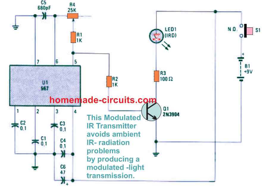
The IR transmitter, demonstrated in Fig. 1 above, is constructed using a 567 PLL (Phase-Locked Loop), which is configured to modulate the IR-light transmissions. Transistor Q1, a 2N3904 NPN unit, is wired for driving a high-efficiency IR LED (LED1).
The PLL is wired like a VFO (Variable-Frequency Oscillator), capable of generating a square-wave output at pin 5. This output is used for feeding the drive current to the base of Q1.
Q1 as a result switches the LED on/off at the rate of the oscillator frequency. The max current current that can reach the IR LED's is restricted to a safe value by R3.
Infrared Receiver
The receiver design can be witnessed from the Fig. 2 below which is designed to be perfectly compatible with our transmitter circuit exhibited in Fig. 1 above.
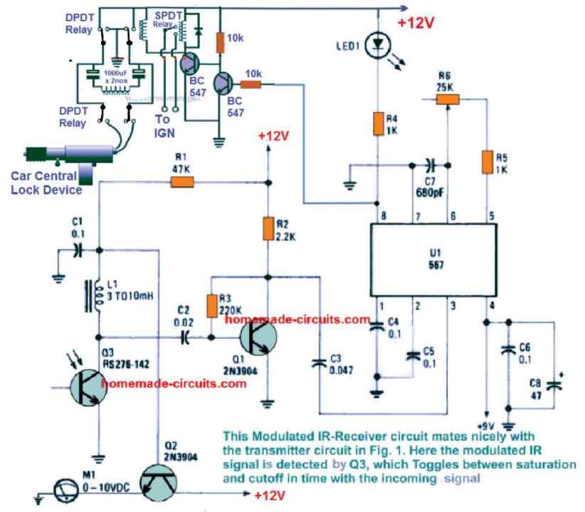
In the above IR receiver circuit, the modulated IR signal from the transmitter is recognized by the phototransistor Q3, which oscillates between the thresholds of saturation and cutoff, synchronized with the transmitter signal.
The AC element of the transmission existing at the Q3 collector is transferred through C2 to the Q1 base for more amplification. Later on, this enhanced signal is applied to U1, which is an another 567 PLL, configured like a decoder circuit and tuned with the identical frequency as the transmitter PLL.
As soon as the transmission IR waves hitting the pin3 input of U1 is at the right frequency and over 50 millivolts, causes the U1 output at pin 8 to be pulled low or to the ground potential activating the relay circuit. This is indicated by an illuminated LED1.
Transistor Q2 tracks the DC part of the received IR signal (which includes all the wanted and unwanted IR radiation striking the phototransistor) indicating the proper processing of the IR beam through the attached voltmeter.
The DC-carrier voltage diminishes as the strength of the IR light increases, therefore a lower voltage level (signal) on the meter implies that a genuinely powerful IR signal from the transmitter is striking Q3.
As long as the voltage at the Q3 collector continues over 2 volts (as indicated on the meter), the receiver works perfectly; however in case the ambient IR striking the phototransistor is very powerful, the voltage could decrease to a level where the actual transmitter's IR beams will never be recognized.
For switching other heavier loads, the LED1 could be replaced with an optocoupler, and thus enable almost anything to be switched on or off with the easy IR remote-control system.
In the present design a transistorized relay driver is used and connected with the pin8 output of the receiver circuit. The relay driver actuates the central lock device of the car in response to the ON/OFF operation of the IR receiver, through the IR transmitter handset.
Integrating with Car Central Lock
A car central lock system is powered by a magnetic solenoid, which pushes and pulls the lever of the lock for implementing the locking and unlocking of the car doors. The following image shows how the car central mechanism works, whose shaft is pulled and pushed by the actuation of an internal geared motor.
This happens when the power or the voltage to the motor is alternately switched with a forward conduction and reverse conduction, by changing the polarity of the input supply.
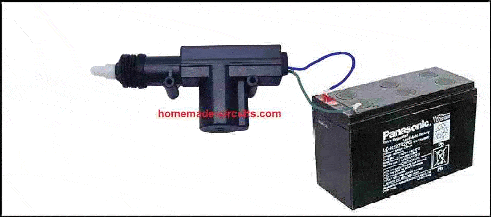
However, it must be noted that the after the solenoid gets actuated, the supply must be immediately cut off to the solenoid, otherwise the solenoid can burn. This issue is effectively taken care of in the relay driver circuit, where a separate DPDT is employed for operating the solenoid, which delivers the current to the solenoid via two 1000 uF capacitors. The capacitors ensure that the current is supplied to the solenoid only momentarily as long as the capacitors are charged, and then it is cut off.
As shown in the IR receiver circuit diagram pin#8 of the IC 567 which is the output of the IC, is connected with the relay driver circuit. Whenever the IR receiver is activated with a compatible frequency, pin#8 goes low, and the relay drivers actuates the car lock solenoid once, which causes the doors to either lock or unlock depending on its initial situation.
When the next activation is carried out by pressing the transmitter IR remote, the solenoid now operate in the reverse direction, causing the appropriate locking or unlocking action on the door locks.
Power Supply
Any well-regulated DC supply from a suitable AC to DC adapter having an output DC of 12 volts at about 500 milliamps could be employed to test the receiver circuit. Once tested on work bench, the circuit may installed and integrated with any vehicle door lock, having a 12 V battery
The transmitter circuit could be constructed on a piece of stripboard and encased inside a little plastic-type box with the IR diode sticking out in one edge of the box.
A small convex lens could be included to both the transmitter/receiver units in order to focus the IR strength for increased working range.


Need Help? Please Leave a Comment! We value your input—Kindly keep it relevant to the above topic!