In this article I have explained an automatic door mechanism circuit that responds to the ambient light conditions by keeping the door open during day time and closed during night. Here the application is used for operating a hen house door. The idea was requested by Mr. Gavin Sweet
Technical Specifications
I have a project that I am starting to investigate and was wondering if you had any ideas
The project is to make an automatic door for a hen house, I would like it to be controlled by dawn/dusk to run a 12v motor to open the door then reaching a limit switch to then reverse motor direction when it is dark returning the door down to a second limit switch placed at the bottom of the door (I was also Hoping to put a delay on the door closure of Upto 30 mins)
There are many designs for a timer version of this circuit but this would mean periodic adjustments to the programmable timer.
I hope you can point me in the right direction
Thanks
Gavin Sweet
Transistorized LDR Sensor Version
The Design
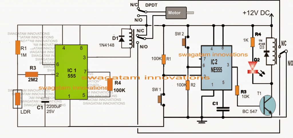
The requested dawn dusk hen house door operator circuit may be witnessed in the above diagram and understood with the help of the following points.
Two 555 IC stages can be seen the proposed design.
The IC1 stage is wired as light activated switch using an LDR as the sensor.
The relay associated with IC1 is held deactivated during day time and vice versa.
IC2 is configured as a set/reset latch flip flop or bistable stage wherein the relay associated with this IC stays activated when SW1 is in the depressed position and deactivated when SW2 is in a pushed ON state.
Let's assume it's day time and the door being fully open, and the door mechanism keeping the SW1 switch pushed ON.
In the above scenario, the IC1 DPDT relay can be assumed to be in the N/C positions, while the IC2 relay in N/O position.
IC2 relay being in the N/O position cuts off the negative supply to the DPDT relay making sure that the motor in this state stays shut off and tightly locked keeping SW1 pressed and ON.
Now, as day light begins to fade and dusk arrives, the LDR senses this and toggles IC1 pin3 low, actuating the DPDT relay whose contacts now change positions towards their respective N/O points.
The above changeover immediately switches ON the motor which starts moving the door mechanism until its fully closed. In the course it releases SW1 rendering IC2 in a standby position.
When the closing procedure ends, SW2 which is positioned at the the other end of the door mechanism responds to the closing of the door pressure resets the IC2 such that its relay now chnages from N/O to N/C. This action instantly cuts off the other negative line to the N/O contacts of the DPDT.aking sure that the motor shuts off again and stays in that position until dawn sets in.
The 2200u capacitor and R3 may be appropriately tweaked for getting a delayed response from IC1 after dawn or dusk transitions are sensed by the LDR


Questions & Answers
is it possible for you to make an example of a circuit schematic of an micro control sensors automatic doors lock system with an led when occupied
Please provide the full working details of your design, it will help me to understand the concept better and to design it…
can i change LDR sensor with IR sensor?
Sorry, no, that may not be possible.
I Change LDR with IR and the circuit work but i have Problem the motor only work in one direction, How can fix that?
Did you wire the DPDT relay correctly with the motor as shown. The given DPDT connections ensure that the motor rotates both ways.
Yes, the common with motor and NC, NO with Vcc. Also( NC with NC and NO with NO to other relay)
When the relay contacts change their positions the polarity of the motor wires become opposite so the motor should also change its rotation direction. You can track the wires of the motor connections with the relay contacts, you can easily see that the polarity of the motor changes when the relay operates.
Can you tell me the function of the resistors and diodes in this electrical circuit
Which resistor and diode?
Hi,
I’ve built this circuit on a breadboard and I’m having a few problems. I’m hoping you can help me find out where I’ve gone wrong.
The main problem is the motor only turns on when SW1 is pressed, and it runs for a varying period before turning off by itself (without me doing anything). If I press SW2 while the motor is running it will stop.
I think one problem is the DPDT is active as soon as I power on the circuit – which I think means the IC1 Pin3 is Low.
Covering the LDR or running the circuit in darkness doesn’t have any effect. The motor still only runs if SW1 is pressed.
The other problem is the motor turns itself off, even if the SW2 hasn’t been pressed.
I hope I’ve explained the problem clearly.
Thanks for your help.
Hi, IC1 DPDT relay should switch OFF (move to N/C contacts) when the LDR is exposed to light, and switch ON (move to N/O contacts) when the light is removed from the LDR.
For the IC2 pressing SW1 momentarily should switch ON the SPDT relay (move to N/O contacts) when SW1 is released and SW2 is pressed then the SPDT relay should switch OFF (move to N/C contacts). Please confirm the above. If these are not happening then something is not correct with your circuit.
By the way breadboard assembly will not work for this circuit, you will have to join the parts by soldering.
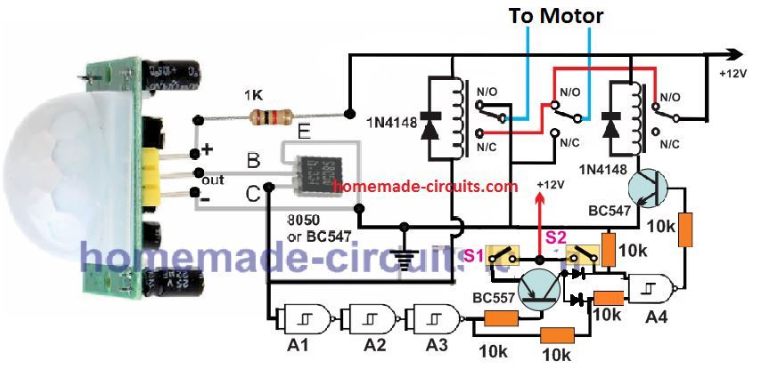
I can provide the same circuit using transistors which can be much easier.
I think the reply function might not be working? my reply keeps disappearing.
Thanks for your quick reply.
I changed IC1 to a new 555. IC1 DPDT is now switched off (N/C) when the circuit powers on, but the LDR still doesn’t have any effect. Should the change be instant or is there a delay? I’ll recheck all my connections to make sure they’re correct. Is there anything else you can suggest?
For IC2 the SPDT is now working properly. When I press SW1 the SPDT moves to N/O, and when SW1 is released and SW2 is pressed it moves to N/C.
Can I use the breadboard to test the circuit before I solder it?
All your replies are all intact, none of them have disappeared… you can check them under the article….I have replied to your previous comment, please check it.
Hi,
Thanks for your quick reply.
I changed IC1 to a new 555. IC1 DPDT is now switched off (N/C) when the circuit powers on, but the LDR still doesn’t have any effect. Should the change be instant or is there a delay? I’ll recheck all my connections to make sure they’re correct. Is there anything else you can suggest?
For IC2 the SPDT is now working properly. When I press SW1 the SPDT moves to N/O, and when SW1 is released and SW2 is pressed it moves to N/C.
Once I have the circuit working I’ll build it properly on a PCB.
Hi, the LDR ON/OFF will not be instant because of the internal hysteresis of the IC and because of C1. Please remove C1 completely for the removing the slow response.
Since your IC2 is now working, that’s great, now you only have to fix the IC1 working. Remove C1 and I think the slow response will be solved.
I wanted to make this but am having a bit of trouble matching parts. Do you have a parts list for this circuit? For that matter do you have parts lists for other circuits?
All the parts exactly as given in the diagram…..the resistors are all 1/4 watt….the part dealer will be able to guide you through…
The only problem is that Digikey.com has variants of the same part. For example NE555 isn’t just NE555 there are a few different types of NE555. I can take a logical guess, but since this is for someones pet I don’t want to guess.
All 555 IC has the same function and same pinout specs, so you can use any of those IC 555
Thanks a lot, I'll try the suggested solutions. I indeed already included C1. I also played with the value of R3 (10k for example), and as expected I can decrease the delay after the threshold is reached. It's at the time the DPDT finally switch to "day mode" that I observed this oscillation.
I'll keep you informed, thanks for the good work and cheers from (exceptionally sunny) Belgium!
You are most welcome!! I wish you all the best!!
Hi Swagatam,
Great circuit, thanks a lot! I just build it, works fine except a small quirk: when the DPDT relay switch to "day mode", it oscillates (ON/OFF) like crazy for a few seconds, then stabilize. The motor runs fine, I'm just a bit worried about the relay longevity.
Any idea of what the cause could be? I was thinking some back EMF from the motor, but obviously since it runs in both directions I can't avoid this phenomenon by using a diode (like you did on the relay's coils).
Thanks a lot!
….by the way did you include C1 in the design?…the delay caused by C1 itself should be enough to stop any kind of stuttering on the relay.
if the above doesn't help, you can use a BC547 transistor driver for the DPDT relay exactly as done for the other relay…and connect a 10uF/25V with base/emitter of this trasistor
Thanks Niceone, I am glad you could build it successfully.
To rectify the issue, just try connecting a 100uF/25V capacitor in parallel with the relay coil or D1, positive of the cap will go to the positive side of the coil, and the negative to the pin#3 side of the IC…I am sure this will solve the problem….
hello sir i hope you doing fine,is it possible to use that circuit above instead of closing the door during evening and then opening while someone block the LDR and then it open and vice versa
hello yohana, the operation can be reversed by simply interchanging the LDR and R1 positions
hi swagatam sir if possible can u provide me ckt dia for digital ic tester using raspberry pi……….
and happy diwali in advance
I am sorry, at the moment I do not have this circuit, if I happen to find it will surely let you know…
Hi thanks for posting this design, I have a couple of questions whilst I source components/make a parts list. Firstly what is the value of the C1 on the IC2 part of the circuit? How will I tweek R3 to delay dusk activation? Finally there is a DPDT switch at the top of the diagram next to the motor, what is its function, is it to provide override facility to operate the circuit/motor on demand if needed?
Thanks again Gavin
Please read the previous comment for the answers…..I have mistakenly written R1 instead of R3, please note this correction….
R1 is for setting the dawn/dusk threshold, whereas R3 is for producing a delay after these thresholds are reached.
Hi, thanks for posting this design, I have a few questions whilst I source components/make a parts list. What is the value of C1 on the IC2 part of the circuit? How will I tweek the dusk part of the operation? There is a DPDT switch at the top of the diagram next to the motor, what is its function, is it a toggle type override switch to test functionality and be able to operate the system on demand if necessary?
Thanks again Gavin
Thanks it's my pleasure!!
The value C1 of IC2 should be 0.01uF.
Increasing the values of R1/C1 in the IC1 stage will proportionately increase the delay period after the dusk threshold is reached, but I am not sure what value would provide 30 minutes delay, it will need to be experimented by trial and error.
The DPDT indication is for the relay, it's not a switch. The relay associated with IC1 is a DPDT type involving a pair of changeover contacts as shown in the figure.
in order to get an override feature, you can add a SPDT switch parallel with the relay contacts of IC2.
Smart idea..keep it up Swagatam.
regards Humphrey
thank you Humphrey.