• Skip to main content
  • Skip to primary sidebar

Homemade Circuit Projects

Need circuit help? Post them in the comments! I've answered over 50,000!

Blog | Categories | About | Contact | Calculators-online
You are here: Home / Timer and Delay Relay / 3 Stage Timer Circuit for Industrial Camshaft

3 Stage Timer Circuit for Industrial Camshaft

Last Updated on July 6, 2019 by Swagatam Leave a Comment

In this post I have explained a simple sequential timer designed for implementing a specified set of actions involving a 3 step relay activation which in turn is used for executing the desired mechanisms. The idea was requested by Mr. Ali.

Table of Contents
  •  Technical Specifications
  • The Design

 Technical Specifications

I look at your site occasionally and this time round I am looking for a 3 stage timer. I have on your site and several others only found 2 stage timers.

I sincerely hope that I am not putting you into any inconvenience by asking you if you could put a schematic together and mail it to me. If there are any costs involved please let me know up front. The requirements are as follows.

Stage 1 is a camshaft which,at the press of a switch, is driven by a windscreen wiper motor from point A to point B in a matter of milliseconds.

At point B stage 1 should swich off and activate stage 2.After approximately 100 to 200 (max) milliseconds stage 2 should switch off and re activate stage 1 and drive it back back to rest.The time factor for stage 1 and 3 should not exceed 3 seconds(again calculated in milliseconds).

(Stage 2 activates a set of heaters through a relay to bond material.) I could play around with the caps and pots if need be to calibrate it to my requirements.

I just have a basic knowledge in this subject ,hence I would appreciate as much detail that you could provide .

Thanking You and looking forward to your response.

Ali.

3 Stage Industrial Camshaft Timer Circuit

The Design

The idea of the proposed camshaft 3-stage timer actuator circuit can be understood with the following points:

Although the idea sounds straightforward, implementing it practically appears to be complex.

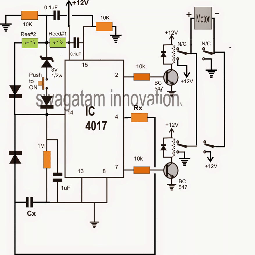
Referring to the figure above, when the circuit is powered, the 0.1uF capacitor across pin15 and the positive of the IC resets the IC to a standby position.

When the shown push button is pushed, pin14 of the IC 4017 receives a clock signal which prompts it to shift a logic high to its pin2, pin2 transistor driver actuates the relay and the connected motor is activated to reach a given destination.

When it reaches the destination, reed#2 which is positioned to anticipate this, activates causing a pulse clock to reach pin14 of the IC, which in turn forces it to shift a logic high from pin2 to pin4. This action instantly stops the motor on the spot.

Simultaneously, the "high" from pin4 yet again causes a pulse to hit pin14 of the IC, however due to the presence of Rx and Cx, it's delayed by around 100 to 200ms. After this period of time, pin14 is toggled which allows the IC to forward the logic high from pin4 to pin7.

Pin7 instantly actuates the connected relay which reverses the motor polarity and reverts it to its original position. At the original position reed#1 is positioned to anticipate this, it actuates and resets the IC through the associated 0.1uF capacitor to the original standby position, for the initialization of the next cycle  via the push button.

For integrating the heater stage, the junction of Rx, Cx can be configured with an identical relay driver stage and the contacts integrated with the heater.

You'll also like:

  • 1.  Timer Controlled Exhaust Fan Circuit
  • 2.  Timer Controlled Fitness Gym Application Circuit
  • 3.  Switching Two Alternate Loads ON/OFF with IC 555
  • 4.  LCD 220V Mains Timer Circuit – Plug and Play Timer
  • 5.  How to Connect 5V Single Channel Relay Module
  • 6.  Simple Delay Timer Circuits Explained

About Swagatam

I am an electronics engineer with over 15 years of hands-on experience. I am passionate about inventing, designing electronic circuits and PCBs, and helping hobbyists bring their projects to life. That is why I founded homemade-circuits.com, a website where I share innovative circuit ideas and tutorials. Have a circuit related question? Leave a comment.... I guarantee a reply!

Previous Post: « Solving Inverter “No Load Auto-Shutdown” Problem
Next Post: How a Connect a Potentiometer »

Reader Interactions

Need Help? Please Leave a Comment! We value your input—Kindly keep it relevant to the above topic! Cancel reply

Your email address will not be published. Required fields are marked *

Primary Sidebar

Subscribe to New Circuit Ideas

Categories

  • Arduino Projects (87)
  • Audio and Amplifier Projects (132)
  • Automation Projects (17)
  • Automobile Electronics (101)
  • Battery Charger Circuits (83)
  • Datasheets and Components (104)
  • Electronics Theory (143)
  • Free Energy (37)
  • Games and Sports Projects (11)
  • Grid and 3-Phase (19)
  • Health related Projects (25)
  • Home Electrical Circuits (12)
  • Indicator Circuits (14)
  • Inverter Circuits (87)
  • Lamps and Lights (142)
  • Meters and Testers (69)
  • Mini Projects (46)
  • Motor Controller (64)
  • Oscillator Circuits (27)
  • Pets and Pests (15)
  • Power Supply Circuits (108)
  • Remote Control Circuits (50)
  • Security and Alarm (64)
  • Sensors and Detectors (101)
  • Solar Controller Circuits (59)
  • Temperature Controllers (42)
  • Timer and Delay Relay (49)
  • Transmitter Circuits (29)
  • Voltage Control and Protection (37)
  • Water Controller (36)

Calculators

  • Battery Back up Time Calculator
  • Capacitance Reactance Calculator
  • IC 555 Astable Calculator
  • IC 555 Monostable Calculator
  • Inductance Calculator
  • LC Resonance Calculator
  • LM317, LM338, LM396 Calculator
  • Ohm’s Law Calculator
  • Phase Angle Phase Shift Calculator
  • Power Factor (PF) Calculator
  • Reactance Calculator
  • Transistor Astable Calculator
  • Transistor base Resistor Calculator
  • Voltage Divider Calculator
  • Wire Current Calculator
  • Zener Diode Calculator
  • Filter Capacitor Calculator
  • Buck Converter Calculator
  • Boost Converter Calculator
  • Solar Panel, Inverter, Battery Calculator
  • Wire Current Calculator
  • SMPS Transformer Calculator
  • IC SG3525, SG3524 Calculator
  • Inverter LC Filter Calculator

People Also Search

555 Circuits | 741 Circuits | LM324 Circuits | LM338 Circuits | 4017 Circuits | Ultrasonic Projects | SMPS Projects | Christmas Projects | MOSFETs | Radio Circuits | Laser Circuits | PIR Projects |

Recent Comments

  • Swagatam on Battery Deep Discharge Protection Circuit
  • Swagatam on 10 LED Tachometer Circuit Diagram
  • Drew Adare on How to Collect Free Energy from Atmosphere
  • Göran on 10 LED Tachometer Circuit Diagram
  • Abdulmajid Haruna on Laptop Power Bank Circuit

Company

  • Privacy Policy
  • Cookie Policy
  • About Me
  • Contact
  • Disclaimer
  • Copyright
  • Videos
  • Sitemap

Social Profiles

  • Twitter
  • YouTube
  • Instagram
  • Pinterest
  • My Facebook-Page
  • Quora
  • Stack Exchange
  • Linkedin
  • © 2025 · Swagatam Innovations