IC 555 adjustable timer explained here can be adjusted from any time delay 1 second to 3 hours for operating any load through a relay control
The produced time delay is fully adjustable and the user has the freedom to set the time period as desired.
There are many ways of making simple timer circuits using different ICs and discrete components; here I have explained one such circuit using the ubiquitous IC 555.
The IC 555 is a pretty common electronic part among the electronic enthusiasts and is also very popular due to the involved simple configurations and low component count.
The two popular multivibrator modes of operation that’s associated with this IC are the astable mode, and the monostable mode. Both of these are useful configurations and have plenty of different applications.
Using the IC 555 in Monostable Mode
For the present adjustable IC 555 timer circuit design we incorporate the second mode of operation, which is the monostable mode.
In this mode of operation the IC is configured to receive a trigger externally, so that it’s output changes state, meaning if with reference to the ground if the output of the IC is zero, then it would become positive as soon as the trigger (momentary) is received at its input terminal.
This change in its output is sustained for a certain period if time, depending upon the external time determining components. Normally the time determining components are in the form of a resistor and a capacitor which together determine or fix the time period for which the IC output would hold its “high” position.
By changing either the value of the capacitor or the resistor, the timing can be altered as desired. The above time fixing components are termed as the RC component.
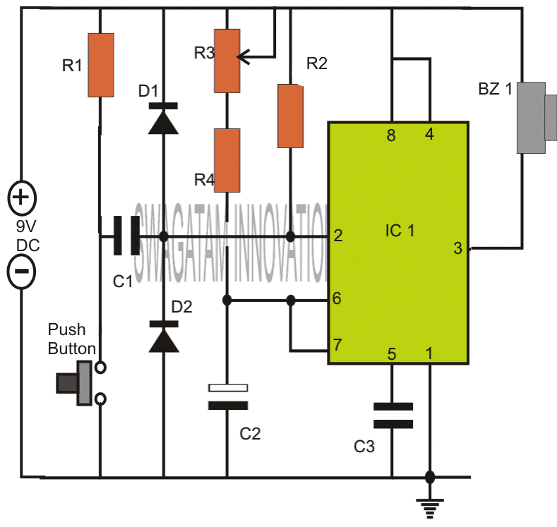
Note: Please connect the buzzer or the load between pin#3 and ground, and not between pin#3 and positive as incorrectly shown in the above diagram.
How the Circuit Functions
The 555 IC timer circuit above shows a very straightforward design where the IC 555 forms the central controlling part of the circuit. As discussed in the above section, the IC is in its standard monostable mode.
Pin #2 receives the external timing trigger from a push-to-ON switch. Once this switch is pushed, the circuit pulls its output to a positive potential and holds it until the predetermined time delay lapses.
The entire circuit can be built over a small piece of general PCB and housed inside a neat looking plastic enclosure along with the battery.
The output may be ideally connected to a buzzer for receiving the warning alarm after the set time lapses.
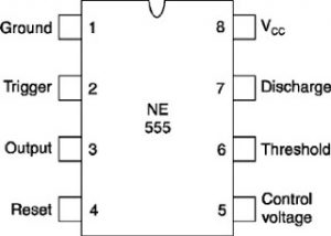
Parts List
- R1, R4 = 4K7,
- R2 = 10K,
- R3 = 1M pot,
- C1 = 0.47uF,
- C2 = 1000uF/25V,
- C3 = 0.01uF,
- IC1 = 555,
- Bz1 = Piezo Buzzer,
Push Button = push to ON switch circuit design requested by Mr.Bourgeoisie:
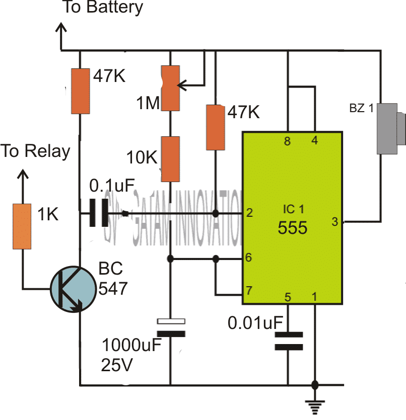
Please connect the buzzer or the load between pin#3 and ground, and not between pin#3 and positive as incorrectly shown in the above diagram.
Timer Circuit with Relay Switching
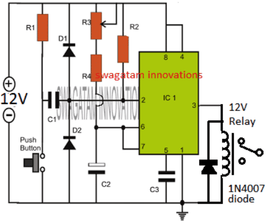
If you are wondering how the above simple timer circuits could be used for triggering a high power load through relay switching, then the following diagram will help you to implement the same by attaching a simple relay stage with the shown designs:
Parts List
All resistors are 1/4 watt 5%
- R1, R4 = 4K7,
- R2 = 10K,
- R3 = 1M pot, Linear
- C1 = 0.47uF Ceramic disc or PPC,
- C2 = 1000uF/25V, Electrolytic
- C3 = 0.01uF, Ceramic Disc
- IC1 = 555,
- Diode = 1N4007
- Relay = 12V/400 Ohm relay,
- Push-button = Any push-to-ON switch
Circuit Operation
In the shown diagram, when power is switched ON, the IC goes into a standby state, and no triggering action is initiated at this moment.
However as soon as the push button pressed, pin#2 is pulled down to ground which instantly triggers the IC in the monostable counting mode, and the relay is activated. The load connected with the relay is thus also activated.
The IC starts counting, and depending on the values of R3/R4, and C2, once the timing period gets elapsed, the IC resets to the previous standby mode deactivating the relay. The relay load also gets deactivated in this situation.
The cycle repeats each time the push button is pressed, enabling the user to achieve the relay triggered timing ON OFF feature in the circuit.
The timing interval can be increased or decreased to a given extent by suitably altering the pot R3 value and/or by modifying the value of C2.
Prototype Images
The above explained 555 adjustable timer circuit was successfully built and tested by Mr. Vee, who is one of the dedicated readers of this blog, and a serious electronic hobbyist.
The circuit was appropriately modified to suit his personal timer application. The modified image can be viewed in the following diagram:
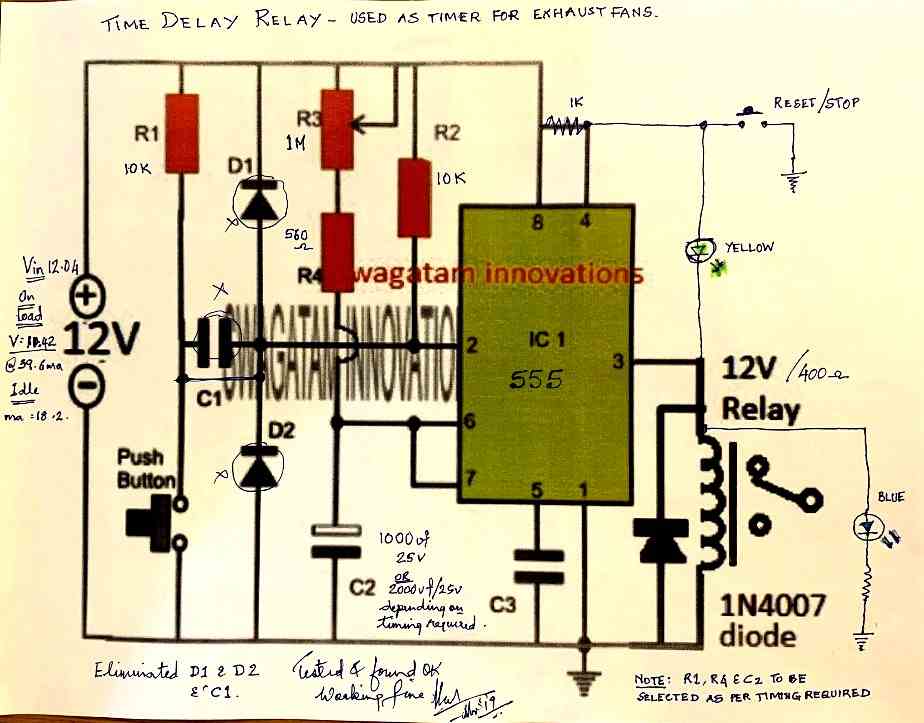
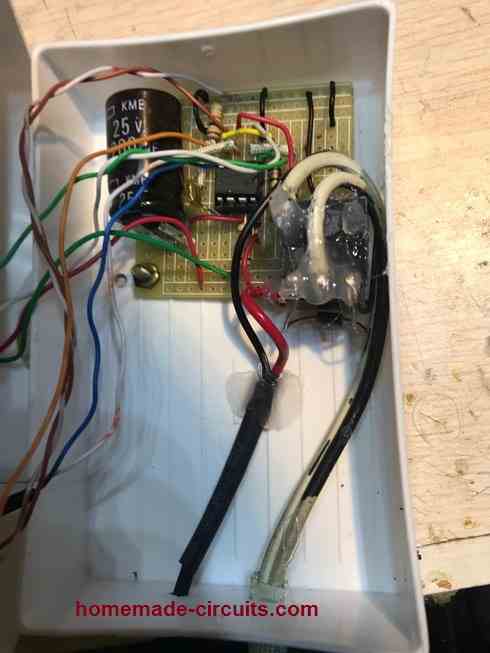
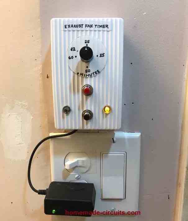
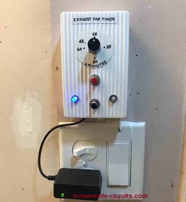
The prototype images of the above timer unit can be witnessed as shown below (built and tested by Mr. Vee):


Questions & Answers
Sir, im SASHIKA from sri lanka. i want to make a polyethene sealer machine for my privet purpose, its hard to find a proper variable timing circuit for it. can you please send me a proper circuit diagram for it.
circuit work direct 230v, and heater work with 12v t/f
Hello Sashika, You can try the 3rd circuit from the above article?

For the 12V operation you will have to use a 12V transformer power supply or an SMS because your heater is 12V.
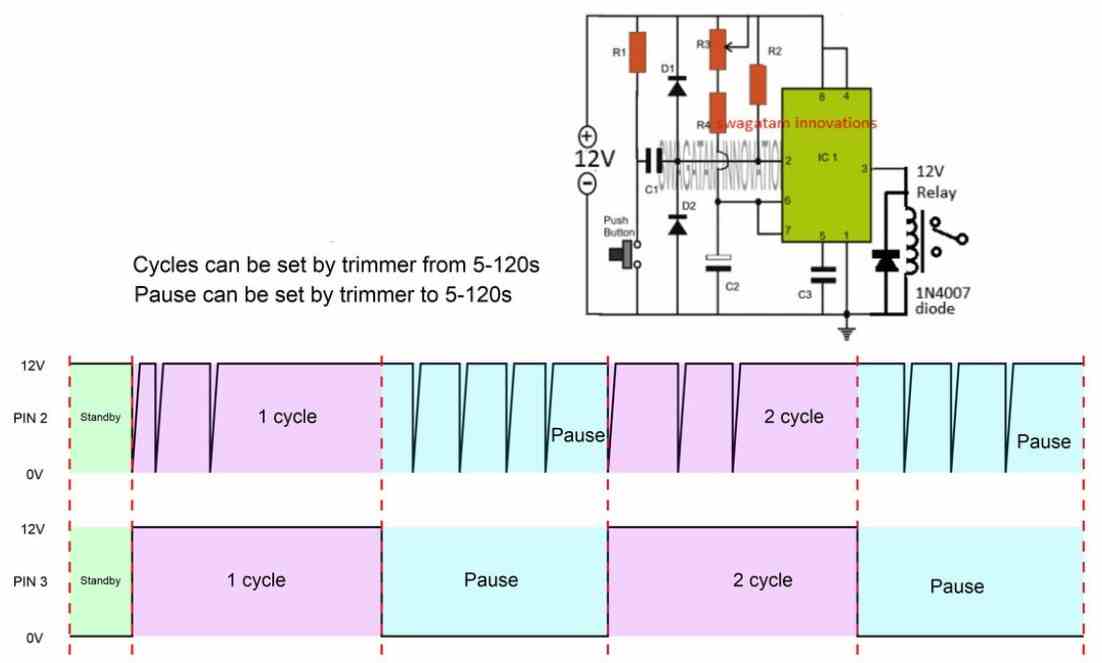
How to add a pause function on this circuit. So, after the end of the first cycle time PIN 3 will remain off for a certain time N seconds, even if the button is pressed several times during that time, after this time PIN 3 will be able to be high again by pressing the button and start another cycle time. In the picture I have shown the working principle of the circuit.
Thanks.
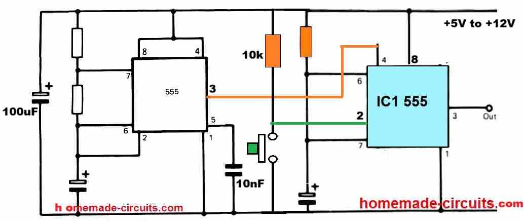
For this you can use another 555 circuit configured as an astable oscillator, and then disconnect the monostable 555 timers pin#4 from the positive line and connect it with the pin#3 of this astable 555 oscillator.
Let me know if you understood the connections or not…
I don’t understand the connection. Can you draw circuit diagram it for me.
Thanks.
You can do it in this way:
It works Thanks. You are genius!
You are most welcome, glad it worked….
Hi Swagatam, I have built the first page monostable 555 ic circuit, It works very well however the output (terminal 3) only energises for 10 minutes max. I require at least an hour, Max 3 hrs, Please advise the correct combination value of the capacitor C1 or C2 + resistors R1, R4 or R2 to obtain the 1 to 3 hours duration. Note: this is required for an automatic watch winder project, Thanks in anticipation,
Kind regards, Derek
Thanks Derek,
For 3 hours delay you will need R3 + R4 = 4.7 MegOhm and C2 = 2200uF/25V
These figures look huge and the time delay may not be accurate due to internal instability of the IC 555.
For accurate results using much smaller parts I would recommend using an IC 4060 timer circuit.
Hi there, I am very interested in using the circuit named “Adjustable timer circuit using I.C. 555” Scrolling down on that circuit using a relay to control bathroom exhaust fan with an ERV in our new home. The circuit Mr Vee uses states he eliminated D1, D2, and C1. I have built a prototype of the circuit as he did, without the reset and stop button, but it just cycles relay on and off depending on value at R3 without pressing the push button and not sure why this is happening. Not sure why he eliminated those parts, but maybe these parts need to be in there. I am not an engineer, but a graduated electronics tech that am capable of building these type of circuits. Could you look at his design and verify his revised schematic? I would be very grateful.
Thank you,
Karl Frey in Ct.
Hi Karl, you have to build the circuit in the following way. This circuit cannot go ON/Of continuously. The relay will be ON only momentarily when the push button is pressed. The momentary relay ON time will depend on the adjustment of the 100K pot and the 100uF capacitor values.
Hello Swagatam
I am in need of a programmable Drag Racing “reaction time” delay box that can be activated from an existing Transmission brake (transbrake) circuit that uses a 12v- (ground activated) normally open, momentary contact switch. The “delay box” would need to be programmable for a range of 0.000 seconds to 9.999 seconds and be adjustable “on the fly” meaning I might have to adjust it from round to round during a race. There are existing delay boxes such as the Dedenbear RTD-6 Reaction Time Delay Box (I have one of these) but all of them are 12v+ switched. The delay box has to be wired “in-line” with the activation switch on the existing transbrake. A conversion circuit would also work and allow me to use my existing delay box. It would need to convert the ground trigger to a positive trigger and back again and be wired to the existing system “in-line”.
Here is an example of what I need BUT it should work off of a ground activated switch instead of a 12v+ switch. http://www.dedenbear.com/TXTrtd.htm
Hello Thomas, To figure out a method to convert the positive triggered time delay box into negative triggered unit I will have to see the wiring diagram of the whole system. Without seeing the full wiring diagram it can difficult for me to suggest the exact solution. By the way I already have drag race timer circuit in this blog, but it uses an optical triggering system instead of a push button.
https://www.homemade-circuits.com/make-this-drag-race-timer-circuit/
Thank you sir for such a fast reply! I did look at the timer circuit you have. That unit is designed to physically time a vehicle in motion over a given distance. Tracks use those to time race cars during each race. What I need is physically inside the vehicle itself and is used exclusively to delay the launch of the car when the light turns green. I have many photos I could send if needed. Please look at the links below. These are the products I have and unfortunately that is the best I can do without being able to send you the photos I have.
https://www.jmschip.com/content/LaunchMAX/JMS_LaunchMAX_Plug_and_Play_web.pdf
http://www.dedenbear.com/instructionswiring/RTD67.pdf
http://www.dedenbear.com/TXTrtd.htm
I hope this helps you. Thank you again.
Hi Thomas,
I am sorry those pics are not helping. I am unable to understand the working condition of the timer you are looking for.
You are saying that the timer unit is supposed to be inside the car and this will delay the launch of the car when a light turns green.
How is the timer integrated to the car?
How is the timer supposed to launch the car?
Where is this green light situated and how can the timer sense this green light?
I can understand the working only if you explain the entire system in a step wise manner.
I think I figured it out. I have a working test unit now. I was able to use a relay to trigger ground instead of positive 12v.
1. I connected one side of the JMS LAunchmax activation lead to 87 on the relay.
2. I then looped 87 to 86 on the relay
3. I connected a 12v lead to 85
4. I connected the other side of the switch from the JMS Launchmax to 30 on the relay.
5. I wired the Dedenbear RTD-6 as I normally would with any manual valve body automatic transmission.
Using a standard transbrake button, when I stage the car I simply push the button. The button activates the RTD-6 which in turn feeds a 12v signal to the relay. When the relay triggers, the transbrake locks the car in position. When I let the button go, the RTD-6 counts down based on the delay I set and then kills the power to the relay and launching the car.
If I had the ability to send you photos, I would send you a photo and/or video of it in action.
That’s great Thomas, Glad the issue is solved now.
Unfortunately there’s no facility to upload images on this platform, I wish I could do it here.
Thanks very much for the detailed circuit description – I now undertans how it works.!
I will head to the local electronics shop and get the components and some veroboard!
Will let you know when we’ve cleaned the first fuel injector.
Many thanks.
Sure, no problem. Wish you all the best!
One last dumb question. Is the positive output at the top of of the load and the negative at the bottom?
Yes, Load top side is the positive side, load lower side which is connected to the transistor is negative side.
Thank you so much. I would really value a description of how the circuit works. From my limited knowledge of electronics, I can see that the capacitors charge up time cause the circuit to switch off and then on again when charged up, but not sure what T1 and T2 do. I also presme that when voltage is applied to T3 it turns the circuit on. Or am I following it incorrectly?
The circuits is a basic transistor astable oscillator. The two capacitors along with the resistors charge and discharge alternately causing the two transistors to switch ON and OFF alternately. The capacitors and the R2, R3 resistors needs to be balanced in order to ensure the ON/OFF switching periods across the two transistors are equal and uniform. This means the values of these components can be altered as desired to change the ON/OFF periods accordingly.
The T3 accepts the ON/OFF signals from the astable oscillator and switches the load ON/OFF with the same interval.
Thank you so very much for the circuit. I presume the load is positive and the pump will be grounded to the circuit at the base?
You are most welcome! The positive of the load goes to the positive supply line, and the negative of the load goes to the collector of the transistor.
I need a simple 555 circuit to drive a 12v relay that can be set to switch on and of from .5 of a second to 2 seconds – please can you help. This is to drive a 12v pump that pushes carb cleaner through a fuel injector to clean it.
Should the operation be a continuous ON and OFF switching? Meaning should the relay be switching continuously ON/OFF with the specified ON/OFF periods?
Yes that is correct. Fuel injectors often have restricted delivery – rather like human arrteries – I have found that using carb cleaner pumped through the injector in short bursts often resolves the problem. For some reason this works better than a constant stream. Having a circuit that turns the pump on and off would do the job perfectly and the whole system could work off a 12v power supply. I am in South Africa and the cost of vehicle spares is very high so being able to repair injectors would be a great help to us. Many thanks for your kind assistance with this.
OK, thanks for the description. You can probably try the following design for your application; The VR1 can be a preset or a pot which can be used for setting the ON OFF periods of the switching.
Hi Swagatem
I’m thinking about building a manual alternator controller/regulator to control the alternator on my (live aboard) sailboat (which I also build)
I’ve found a circuit that includes a temperature sensor for the alternator. Would you mind having a look (picture emailed) and making sure it’ll do what it’s supposed to, and maybe suggest any way to improve it (safely and efficiency)
I’ve got a voltmeter with a relay output which could be used to trigger the opening of a relay in the event of a overvoltage (for whatever reason).
The picture shows the potmeter located on the circuit board. Do you think there’s any problem having the potmeter remotely located, roughly 10ft away from the engine?
Best Regards
Hi Neil, the diagram which you have sent does not look efficient to me, I am not sure if it will do the job correctly or not.
However, we can’t discuss it here since it is not right place to discuss.
For further comments please post them under the following article, I will try to help:
4 Solid-State Car Alternator Regulator Circuits Explored
Hello sir,
I want to make an automatic timer switch circuit who would automatically turn off after 60 minutes and other specification of load circuit (has heating element) are that it works on 5V, 3A.
please guide me with this.
Hello Shivani, you can refer to the following article and build the relay based design:
https://www.homemade-circuits.com/how-to-make-simple-versatile-timer/
You can increase the C1 value to any higher levels in order to increase the range of the timing output. However make sure the capacitor is non-polar type only. Alternatively, you can also use 1uF non polar capacitor and put any number of these capacitors in parallel to increase the timing range to any desired levels.
Thankyou so much sir it is very helpful, Can you please share your LinkedIn id too?
You are welcome Shivani, My Linkedin ID is: https://www.linkedin.com/in/swagatam-majumdar-53568423/
Dear sir,
I am very much impressed with your work. I was searching for a time delay Circuit
for my RO Auto flush. Can you provide me the same..? When the power is turned on
the RO Auto flush will work for approximately for 18 seconds, and the power to the relay
is turned off.
Thank you Hary, you can probably refer to the following article for the solution:
Simple Delay Timer Circuits Explained
Hi Swagatam
Thanks for your reply and suggestions about a slow charger, yes thats true
All the best to you
Regards
Vee
You are welcome Vee!
Hi Swagatam
Regarding the mobile internal cutoff for charging circuit, I understand it is supposed to be there, but I’ve read many articles regarding this and it is recommended to keep the charge between 30 & 95% and Ive practically seen this helps as I do this and have never replaced my iPhone battery in years. I’m a bit confused now
Anyway thanks for the info
Regards
Vee
Hi Vee, as far as I know, all mobiles have a sophisticated charger internally which knows exactly when to cut off the battery charging. However, using a charger that could charge the phone with a duration 2 hours or more, can help to maintain a longer life for the phone battery, because batteries always like slow charging, and at lower temperatures.
According to me you don’t have to add anything externally to enhance the battery life, just make sure that the charging slower, which will also mean allowing lower temperatures for the battery.
Hi Swagatam
I have built a time delay relay using 555 IC with a timing upto about 1 hour, I understand that the 555 has its limits of the RC of upto 1 meg and 2200 cap.
I would like to build a time delay relay from 10 mins to 2 hours in steps of 10 mins to use it with my cell phone charger to avoid over charging my phone as it is recommended to keep your phone charged between 30 & 95% not more to avoid over charging and bulging the battery
I tried making one with the IC 4060 but it’s unstable I don’t know why
Please help & thank you very much
Regards
Vee
Hi Vee,
all cellphones already have an internal over charge cut-off circuitry, so even if you connect the charger permanently or forever with your mobile phone that still won’t damage anything in the phone.
Regarding the timer, since the 555 timing capacitor is the main component that determines the timing output of the IC, you can put several capacitors of incrementing values, and use a selector switch to toggle across the capacitors, so that it allows you to get the desired timing in steps.
Ic 4060 is a highly stable timer IC, since it is a CMOS based IC…it is much more stable and accurate than a IC 555 timer. You can you recheck your circuit to ensure everything is connected properly.