The following regenerative electricity generator circuit in cars and motorcycles was inspired from the oscillating dolls, and idols inside vehicles which may be seen constantly swaying and moving due to the vehicle's uneven motion or whenever brakes are applied.
How Energy is Wasted in Vehicles During Braking
Whenever a vehicle is stopped or braked, a huge amount of energy is wasted in the process, and an equivalent amount of energy is further wasted while the vehicle in restarted. A simple motor generator concept helps to extract valuable free electricity from cars and vehicles whenever brakes are applied or even while the vehicle is moving with frequently altering speeds.
I have already discussed an interesting article regarding how to convert your vehicle braking system into a efficient regenerative braking system, here we apply the same concept but not for assisting the vehicle rather for using the electricity for any alternate use such as for charging a cellphone, battery etc.
Using Fly-Wheel and Pendulum Concept
The idea is quite basic, we do this by combining a motor generator with a pendulum or a flywheel concept for acquiring a consistent free energy from any moving vehicle where it has been installed.
The following figure shows a simple motor pendulum set up where the pendulum is developed in the form of a circular load with a dislocated center of gravity towards the periphery of the circle.
The pendulum load could have any other preferred structure, although the shown design provides the highest possible efficiency due to minimum air drag.
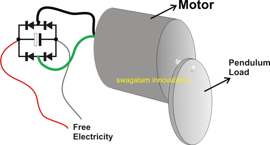
The pendulum is fixed with the motor shaft, such that whenever the pendulum moves the motors internal coil magnet mechanism also undergoes an equivalent amount of movement which ultimately helps in the intended electricity generation.
How the Free Energy is Acquired Using a Motor Generator
The getting electricity from regenerative braking action is very basic. The motor here operates in the opposite mode, that is in the generator mode and generates electricity whenever the pendulum moves, which in turn happens when the vehicle undergoes an uneven speed pattern.
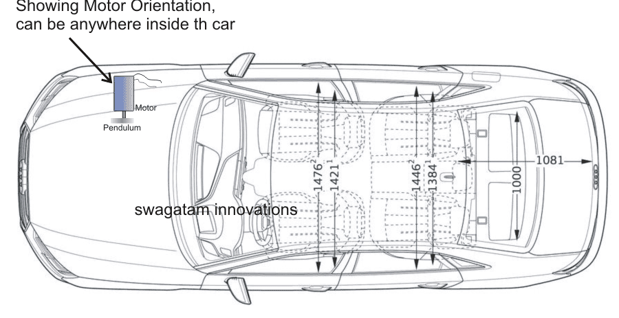
The indicated set up simply needs to be clamped inside any vehicle laterally such that the axis of the system is parallel to the width axis of the vehicle. The location could be anywhere and is not critical.
Once installed, the motor generator could be expected to instantly or consistently produce different levels of electricity depending on the speed changes of the vehicle or the rate of braking of the vehicle.
Since the pendulum oscillations range could be limited to a 90 degree swing on either sides, the generated voltage levels could be proportionately limited compared to full rotations, therefore it is advised to use a motor having a relatively higher voltage spec, at around 12 to 24V, which would possibly allow an output of around 2 to 4V, depending on the vehicle's speed or braking levels.
The output could be directly connected to a cellphone for enabling a quick charging of the phone through this free electricity generator concept in cars or any vehicle.


Questions & Answers
In an EV the batteries used can only be recharged (regen) at a certain rate (Amps) and then discharged (accelerated) at a certain (somewhat higher) rate.
That means that only a small fraction of the power generated during regen can be recaptured.
Super/Ultra capicitors can easily ‘take’ the extra charge generated during braking and then supply the extra amps required for acceleration.
ie: Supercaps have the Power Density desired for EVs, but not the Energy Density.
So, ideally, one wants both batteries and SuperCaps in an EV, with a circuit that sends some of the amps to the battery during regen, with the (larger) remainder going to the supercaps, and visa-versa on acceleration.
There’s also the ‘voltage drops linearly with discharge’ in SuperCaps issue to overcome.
Do you have any ideas on how this might be easily and simply achieved?
(I have been thinking about a:
– supercap -diode(and??)> battery -diode> supercap +
in series arrangement to simplify the required electronics…?? Possibly with the supercaps operating at a higher voltage than the battery..? )
Yes, it is possible to create this type of arrangement with a relatively circuit, provided the regenerative power is sufficiently high, otherwise the result won’t have much impact…
I will try to design it soon, and let you know.
Hi Swagatam,
I saw a citation about the Electromatic car, but could not find the text affiliated with it.
Could you point me to it or email it to me?
I knew Wayne. Long story.
Hi Woody, I am sorry, I tried to find it, but it seems there’s no sufficient information regarding this concept anywhere on the internet.
Some of the other Suppressed inventions that I’ve studied are high mileage carburetors, how they work is they turn the gasoline into a dry (not a wet) vapor, by burning this type of vapor you get complete combustion and better mileage and longer engine life too. Some of the inventors were Charles Pogue, Tom Ogle, Ray Covey, and Larry Wagner. Another free energy device is the hydrogen generator, one such unit was invented and tested by Stanley Meyers, but shortly after a televised test of his car he was killed and his car disappeared! (stolen!) his system created hydrogen on demand from water using no electrolytes!
In the 80’s I bought some Perpetual Motion Books, (in the USA) one idea that is still quite promising was designed by Wayne Henthorn called Electromatic (electric) motor car. How it worked: the car was powered by a 12 hp 72 volt dc electric motor, he used another differential (on the front axle) and pulleys to drive (4) Alternators, one put out 12 vdc to charge the 12v batt and the other (3) generated 24 vdc and were wired to charge each of the 24 volt deep-cycle lead-acid battery, The Henthorn design was tested by the world federation of sciences and engineering of Westminster California and it achieved a range of 300 to 500 miles on a charge (using deep-cycle-lead-acid-batteries!)
Hi Clair, are you still actively researching? I met Stan and Wayne…
Hmm.. very interesting facts you have shared, thanks for posting and enlightening the visitors here!