In this post I have explained a voltage high current doubler circuit which will almost double the voltage that's been applied at the input (up to 15V max), and also it becomes specifically useful since it allows higher current loads to be used at the output, in the order 10 amps.
Since the voltage doubler circuit explained here is able to handle high current loads, the design becomes ideally suitable for applications like heaters and high voltage LED lamps.
Circuit Operation
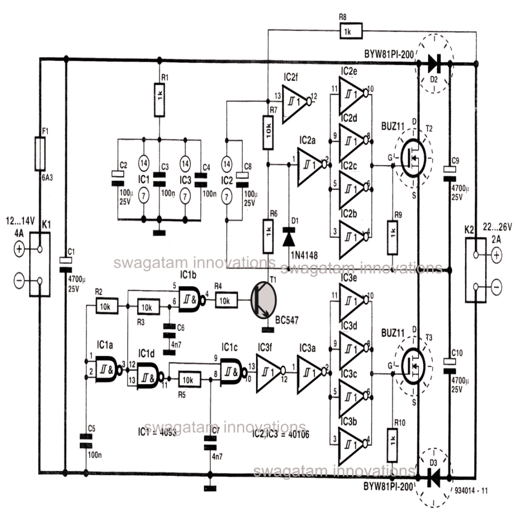
Looking at the given circuit diagram, let's assume we apply a 12V at the input of the circuit, the output would generate a potential of around 22V.
The circuit initiates its functioning when IC1a, R2 and C2 starts generating rectangular waves.
This signal also reaches at the output of IC1d, albeit in an inverted mode.
The presence of R2, C2 delays the output of IC1a which causes the output of IC1b to attain less than 0.5 duty factor, resulting in a waveform where the negative half may be shorter than the positive half).
The above also becomes true at the output of IC1c, were the input data is delayed with the help of C7, R5.
The output from IC1c which is in an inverted form is further buffered thrice via IC3f, IC3a and the gates in parallel IC3b-----IC3c.
The output from the above is finally used for driving the power mosfets.
The transistor T1 is driven from the output of IC1b..... when T1 is ON, the point between R6, R7 attains a 2V potential, however since IC2a requires a 11 to 22V input, the negative potential for this chip is plucked from the positive of the input voltage, because the supply voltage and the collector of T1 is already subjected with the doubled voltage.
D1 is introduced to guarantee that the input to IC2a never drops below 10.5 V.
During the conduction periods of T1, T2 and T3 conduct alternately.
When T2 is switched ON, C10 gets charged with voltage equal to the input supply voltage through T3 and D3.
When T2 is turned OFF, and T3 gets ON, C9 goes through identical process as C10 above. However C10 holds the charge due to the presence of D3 which stops it from discharging.
Because the two capacitors are in series, the net voltage now attains a level that's almost twice that of the applied input voltage.
One interesting thing here is, since the circuit involves many inverting stages and also a few delay networks, the output mosfets can NEVER conduct together which makes the circuit extremely safe with the operations.
C1 buffers the input applied voltage in order to load the input with constant power irrespective of the varying current parameters across the output.
The components which are marked with dashed circles need to be appropriately cooled by adding large heatsinks to them.


Questions & Answers
Solar panels’ voltage should not be boosted when light levels are low. Current draw should instead be reduced or switched to stores of charge instead. Solar panels will produce even less power if their voltage is drained too low.
Correct, unless the load is a low current load.
Dear Swagatam,
Can you call me on 9974675941 ? I may have interesting real life problems on this circuit as well as consulting assignments on some of the other articles I read.
I am sorry Naresh, I am not available on phone, I can only assist through this comment platform.
Hi Pat, sorry this type of voltage doublers won’t be able to handle even anything near 1 amp, so 10 amp may be out of question, however you can try the following option which could fulfill your requirement
https://www.homemade-circuits.com/simple-dc-to-dc-high-current-voltage/
12VDC to 18VDC high current amplifier with 80 Amp output – Do you have a high current circuit in the range of 20 to 80 Amps?
We are in the design choice phase of this project, so a couple of possibilities are;
1) The application could be driven by a 6 volt battery in series with the 12 volt vehicle battery/alternator. A grouping of 6 volt lithium-type batteries could be dynamically switched (regrouped) to 12 volts for recharging from the 12 volt vehicle alternator and then, "on demand", used in series with the vehicle 12 volt vehicle battery to supply the required 18 volts, or preferably,
2) Use a 12 to 18 volt "charge pump" converter that would eliminate the need for the extra batteries and complex switching circuitry. Multiple circuits in parallel could be used to generate the 80 Amps.
The 12 volt supply is a single mobile vehicle battery with a conventional alternator keeping the 12 volt battery charged. We appreciate that this current draw is beyond the capacity of the alternator to "keep up" during the short-term demand, but that is acceptable since this demand will be infrequent so the main 12 volt battery won't become discharged.
deepakrajbar241@gmail.com
if u have a 24 volt 35 amp. to step up the dc voltage
DC-DC voltage doubler 24v- 48v
35 amp.
when you boost voltage the current will drop, so it cannot be 48V 35 amp, it will be 48V, 17 amp
You can probably do it with the first circuit shown in the following article
https://www.homemade-circuits.com/2015/10/calculating-inductor-value-in-smps.html
for the inductor you can use just a few turns may be 3 to 4 turns by winding many thin enameled copper wires together over a ferrite rod.
the 0.6 ohm and the BC547 can be eliminated.
the TIP122 will need to be replaced with any 30V/100amp mosfet N-channel.
the frequency and the PWM may be tweaked for getting the best possible outcome as suggest in the article.
the mosfet will require a large heatsink
Dear Mr. Swagatam,
Your circuit is great, but I need a booster circuit which can give me 5v and at least 1A current from a Li-ion batt (3.7v 2200 ma). Would you please give me any suggestion to make that circuit?
Dear Sadiqul,
you can try the first circuit from the following link:
https://www.homemade-circuits.com/2015/11/make-this-power-bank-circuit-using-37v.html
Hi Swagatam,
Is there a way to modify existing laptop AC>DC charger so that it will have input 12DC (tobe use in car)? FYI laptop model HP EliteBook 2530p, charger output 18.5V 3.5A, 65W. Thanks.
Hi a2b2,
Sorry there's no way to modify the charger, rather you can use or make a 12V to 220V inverter circuit and then use its output to feed the charger input
part number of components used?
Thank you for the great circuit. I have a 12v 10A power supply that I need to get a little more voltage out of it. I would like to use the entire 10A however. Would this circuit be possible to modify to make 15 or 16v output from 12v? Thanks!
Sorry that isn't feasible with any circuit. A higher voltage from a lower voltage source can be acquired only by sacrificing a proportionate amount of current such that the V x I value always remains equal.
power will always remien same for input and output, so here the current is dropped for boosting voltage.
If the current level after the drop matches the battery charging rate, then it will charge the battery optimally.
Nowhere I have mentioned that's it's my creation, in fact there are quite a few diagrams which I have borrowed from Elektor electronics and I have expressed it in those particular articles.
All explanations are completely mine though, so may be while writing the post I missed the credit completely, because for me making the new hobbyists learn about any concept is too important and folks here are appreciating me a lot for that.
I have added the water mark so that others do not pick it from here easily, because already hundreds of my original creations have been scraped online by different spam sites.
If you have the name of the author you can provide it to me I will make sure it gets credited appropriately.