In this post I have explained how to make a simple electric wheelchair circuit using a standard BLDC motor driver circuit, and a couple of high power BLDC motors.
Introduction
The introduction of electric wheelchair was like a boon to our many differently-abled friends who now find it much easier to move and travel around, effortlessly, with just a push of a button.
The only costly and complicated part in a wheel chair design is its ergonomic calculations, and the wheel mechanism efficiency, whereas the electronics for controlling the system seems to be comparably less costlier and complex.
If a manufacturer has the access to the most effective ergonomic design of the wheel chair then making the electrical/electronic section of the system can be quickly implemented by implementing the steps as explained in the following explanation.
Specifications
To make an electric wheelchair circuit the main components required for this may be as per the following list:
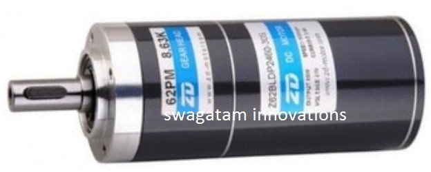
1) BLDC Motors - 2nos (250 watt each)
2) Wheelchair body assembly
3) BLDC Driver Circuit
4) Deep Cycle Battery or preferably Li-ion - 2nos each 24V 60AH
Except the BLDC driver circuit rest of the materials can be procured readymade from the market.
Although I have presented many BLDC driver circuits in this website, I'll be selecting the one which looks more promising and effective due to its flexible features in terms of motor specs and power handling capacity.
In the last post I discussed a relatively simple yet universal BLDC driver circuit using the IC ML4425, and will be employing the same design for our present electric wheelchair motor driver circuit.
Due to its sensorless specs, the circuit allows you to incorporate any type of 3-phase motor regardless of whether it has sensors or not, and without any constraints to the current (Amp) limit required for driving the motor.
The complete schematic can be witnessed in the following image:
Circuit Diagrams
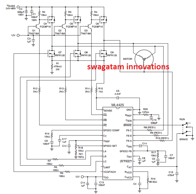
The technical specs for the above sensorless BLDC driver have been already explained in our previous post, therefore you may refer the same for learning the details in-depth.
The controls are actually quite easy and would enable effortless control and maneuvering for the user operating the wheelchair.
The RUN/BRAKE switch could be a single heavy duty DPDT switch which can be used by the operator to instantly stop the wheelchair, whenever required.
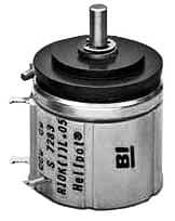
Speed of the wheelchair circuit could be simply controlled by sliding the R18 knob clockwise/anticlockwise. This pot must be of very good quality, preferably a multi-turn type, as shown below.
Potentiometer Specifications
The supply voltage has a wide range, starting from 24V to 80V, which means more batteries could be connected in series to operate higher voltage rated motors, which in turn would allow the manufacturer to incorporate smaller sized motors and batteries, ensuring compact and lighter wheelchairs.
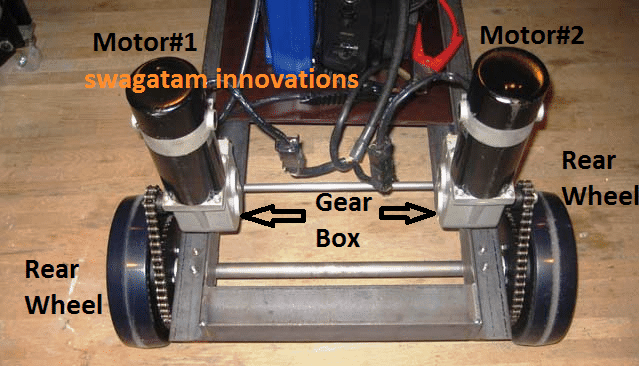
Both the motors coupled with the rear wheels could be joined in parallel and driven using the above shown BLDC driver circuit.
If you have any specific queries regarding the above explained electric wheelchair circuit using BLDC motor, do not hesitate to express them through the below given search box.
UPDATE:
The above design lacks the crucial motor reversing feature, an improved design having a reversing feature can be found in the following pdf datasheet:
https://www.homemade-circuits.com/wp-content/uploads/2018/04/BLDC-driver.pdf


Questions & Answers
Just here is the circuit I was referring to…
Very Simple BLDC Motor Driver Circuit using only MOSFETs and a few Diodes
Now the question is, how do I connect it to a motor that only has 3 wires?
Thank you very much
Hello good morning Mr. Swagatam thank you for your quick response. But I was referring to a simple circuit, for example I have seen on the Internet that there are very simple homemade circuits made with 3 mosfet, some resistors, diodes and a potentiometer to test BLDC motors of washing machines just to know if the motor works…. That’s what I was referring to… Thank you very much.
Thanks Carlos,
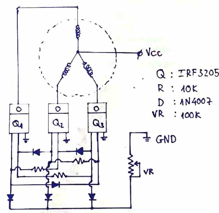
You are right, you can definitely try the following simple design, although I have not tested it so can’t confirm its efficacy:
I forgot that there are also refrigerators that also use BLDC motors….
Yes, that’s right…
Hello swag how r u,
In ml4425 circuit q1,2,3 tn 6718a not avaible does i can use D667 there?
Hello Glabkhan, you can use any transistors which an handle 100 V. If D667 is rated to handle 100V then you can use it.
boa noite, pode ser usada ponte trifasica tipo N apenas? e não P +N?
Hello good afternoon Mr. Swagatam. In this opportunity I would like to ask you for a relatively simple circuit to test BLDC motors since I am seeing that several appliances today use BLDC motors…. Colmo for example the washing machines use bdc in the drain pump, the main motor and also others as ls part of sacado also use BLDC motors… Some circuit to test them. Thank you very much.
Good Morning Carlos,
Most BLDC motor are sensor based motors which can be tested only through specialized driver ICs.
You can consider the following simple driver concepts for testing a BLDC motor if the voltage parameter marches:
https://www.homemade-circuits.com/?s=BLDC
Hi
With R18 you can increase or decrease the speed. Also as suggested, both motors can be hooked together for similar operation. How would you implement turning operations?
Can a joystick be used for operating the speed of the motor and also the left/right turn operations?
Hi, Left/right turning can be done by simply reducing the speed of one of the motors. Reducing left motor speed will force the wheel chair to turns left, and vice versa.
How would you reverse the wheel chair?
using a DPDT switch if the Ha, Hc are flipped and interchanged with each other…. simultaneously with La, Lc should enable a reverse rotation of the motor
ty… i’m looking to use a micro controller to run this circuit throttle control…
If you have the codes then surely you can try implementing it…