In this post I will show how to construct a 10 channel remote control switch circuit based on ISM (industrial, Scientific and Medical) band.
Introduction
The ISM band is operated at 2.4 GHz, which can be used without licensing with reasonable power output.
The proposed project is general purpose ON/OFF wireless switch, which can be utilized to turn ON/OFF Lights, fans, home appliances to home automation if are confident enough to bring hardware or software alterations to this project.
The project is divided into two parts: The remote and the receiver.
The Remote Controller:
The remote controller consists of 10 push buttons for controlling 10 individual relays at the receiver. The remote is operated by 9V battery which makes it portable.
The Heart of the project of is 2.4 GHz transceiver module NRF24L01 which makes the communication between two Arduinos possible.
The Remote sports an acknowledgement LED.
The acknowledgement LED will light up momentarily every time when we press a button on the remote and only if the transmitted signal is received by the receiver and then the receiver send a feedback signal back to remote to trigger the LED.
This process will ensure the remote controller’s ON/OFF command is reached its destination with visual confirmation.
An ON/OFF switch is provided in remote controller’s circuit for preventing from excess energy loss while at idle.
Arduino Nano or Arduino Pro-mini is recommended for constructing the remote as it is in a smaller form factor which makes portable.
Circuit Diagram:

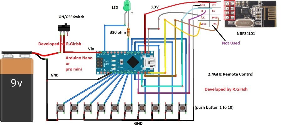
The above is the complete circuit diagram for the remote controller. The pin connection diagram for NRF24L01 is also given in the same schematic.
Turn off the remote when you are done.
Please download the library file here: github.com/nRF24/RF24.git
Program for Remote:
//-----Program Developed by R.Girish----//

#include <RF24.h>

#include<SPI.h>

RF24 radio(9,10);

const byte address[][6] = {"00001", "00002"};

const int ip1 = 2;

const int ip2 = 3;

const int ip3 = 4;

const int ip4 = 5;

const int ip5 = 6;

const int ip6 = 7;

const int ip7 = 8;

const int ip8 = A0;

const int ip9 = A1;

const int ip10 = A2;

const int buzzer = A3;

char buzzchar[32] = "";

const char constbuzzer[32] = "buzz";

const char button1[32] = "activate_1";

const char button2[32] = "activate_2";

const char button3[32] = "activate_3";

const char button4[32] = "activate_4";

const char button5[32] = "activate_5";

const char button6[32] = "activate_6";

const char button7[32] = "activate_7";

const char button8[32] = "activate_8";

const char button9[32] = "activate_9";

const char button10[32] = "activate_10";

void setup()

{

pinMode(ip1, INPUT);

pinMode(ip2, INPUT);

pinMode(ip3, INPUT);

pinMode(ip4, INPUT);

pinMode(ip5, INPUT);

pinMode(ip6, INPUT);

pinMode(ip7, INPUT);

pinMode(ip8, INPUT);

pinMode(ip9, INPUT);

pinMode(ip10, INPUT);

pinMode(buzzer, OUTPUT);

digitalWrite(ip1, HIGH);

digitalWrite(ip2, HIGH);

digitalWrite(ip3, HIGH);

digitalWrite(ip4, HIGH);

digitalWrite(ip5, HIGH);

digitalWrite(ip6, HIGH);

digitalWrite(ip7, HIGH);

digitalWrite(ip8, HIGH);

digitalWrite(ip9, HIGH);

digitalWrite(ip10, HIGH);

radio.begin();

radio.openWritingPipe(address[1]);

radio.openReadingPipe(1, address[0]);

radio.setChannel(100);

radio.setDataRate(RF24_250KBPS);

radio.setPALevel(RF24_PA_MAX);

radio.stopListening();

}

void loop()

{

if(digitalRead(ip1) == LOW)

{

radio.write(&button1, sizeof(button1));

radio.startListening();

while(!radio.available());

radio.read(&buzzchar, sizeof(buzzchar));

if(strcmp(buzzchar,constbuzzer) == 0)

{

digitalWrite(buzzer, HIGH);

delay(500);

digitalWrite(buzzer,LOW);

}

radio.stopListening();

}

if(digitalRead(ip2) == LOW)

{

radio.write(&button2, sizeof(button2));

radio.startListening();

while(!radio.available());

radio.read(&buzzchar, sizeof(buzzchar));

if(strcmp(buzzchar,constbuzzer) == 0)

{

digitalWrite(buzzer, HIGH);

delay(500);

digitalWrite(buzzer,LOW);

}

radio.stopListening();

}

if(digitalRead(ip3) == LOW)

{

radio.write(&button3, sizeof(button3));

radio.startListening();

while(!radio.available());

radio.read(&buzzchar, sizeof(buzzchar));

if(strcmp(buzzchar,constbuzzer) == 0)

{

digitalWrite(buzzer, HIGH);

delay(500);

digitalWrite(buzzer,LOW);

}

radio.stopListening();

}

if(digitalRead(ip4) == LOW)

{

radio.write(&button4, sizeof(button4));

radio.startListening();

while(!radio.available());

radio.read(&buzzchar, sizeof(buzzchar));

if(strcmp(buzzchar,constbuzzer) == 0)

{

digitalWrite(buzzer, HIGH);

delay(500);

digitalWrite(buzzer,LOW);

}

radio.stopListening();

}

if(digitalRead(ip5) == LOW)

{

radio.write(&button5, sizeof(button5));

radio.startListening();

while(!radio.available());

radio.read(&buzzchar, sizeof(buzzchar));

if(strcmp(buzzchar,constbuzzer) == 0)

{

digitalWrite(buzzer, HIGH);

delay(500);

digitalWrite(buzzer,LOW);

}

radio.stopListening();

}

if(digitalRead(ip6) == LOW)

{

radio.write(&button6, sizeof(button6));

radio.startListening();

while(!radio.available());

radio.read(&buzzchar, sizeof(buzzchar));

if(strcmp(buzzchar,constbuzzer) == 0)

{

digitalWrite(buzzer, HIGH);

delay(500);

digitalWrite(buzzer,LOW);

}

radio.stopListening();

}

if(digitalRead(ip7) == LOW)

{

radio.write(&button7, sizeof(button7));

radio.startListening();

while(!radio.available());

radio.read(&buzzchar, sizeof(buzzchar));

if(strcmp(buzzchar,constbuzzer) == 0)

{

digitalWrite(buzzer, HIGH);

delay(500);

digitalWrite(buzzer,LOW);

}

radio.stopListening();

}

if(digitalRead(ip8) == LOW)

{

radio.write(&button8, sizeof(button8));

radio.startListening();

while(!radio.available());

radio.read(&buzzchar, sizeof(buzzchar));

if(strcmp(buzzchar,constbuzzer) == 0)

{

digitalWrite(buzzer, HIGH);

delay(500);

digitalWrite(buzzer,LOW);

}

radio.stopListening();

}

if(digitalRead(ip9) == LOW)

{

radio.write(&button9, sizeof(button9));

radio.startListening();

while(!radio.available());

radio.read(&buzzchar, sizeof(buzzchar));

if(strcmp(buzzchar,constbuzzer) == 0)

{

digitalWrite(buzzer, HIGH);

delay(500);

digitalWrite(buzzer,LOW);

}

radio.stopListening();

}

if(digitalRead(ip10) == LOW)

{

radio.write(&button10, sizeof(button10));

radio.startListening();

while(!radio.available());

radio.read(&buzzchar, sizeof(buzzchar));

if(strcmp(buzzchar,constbuzzer) == 0)

{

digitalWrite(buzzer, HIGH);

delay(500);

digitalWrite(buzzer,LOW);

}

radio.stopListening();

}

}

//-----Program Developed by R.Girish----//
That concludes the Remote controller circuit.
The Receiver:
The receiver circuit consists of Arduino which can be of your choice, 10 current limiting resistors of 330 ohm, 10 transistors and 10 relay forms the output stage.
At each of the 10 output pins of Arduino is connected to 10 relays via resistor and transistor.
Please ensure your power supply is capable of providing at-least 1A of current which is necessary to operate multiple relay at an instant.
A 2.4 GHz transceiver module NRF24L01 provides communication between remote.
Circuit Diagram:
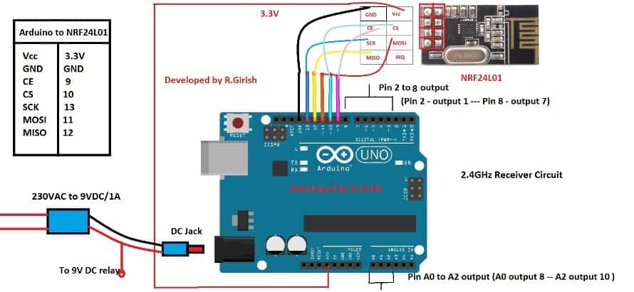
If you are confused with wiring diagram between Arduino and NRF24L01 module, just take a look at the table beside the schematic, it is same for remote controller circuit too.
The output sequence and output pins are as follows:
Arduino PIN – Output sequence
PIN 2 – OUTPUT 1
PIN 3 – OUTPUT 2
PIN 4 – OUTPUT 3
PIN 5 – OUTPUT 4
PIN 6 – OUTPUT 5
PIN 7 – OUTPUT 6
PIN 8 – OUTPUT 7
PIN A0 – OUTPUT 8
PIN A1 – OUTPUT 9
PIN A2 – OUTPUT 10
Output Stage:
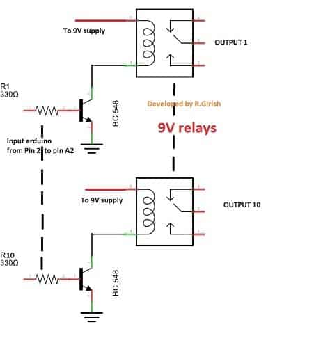
The output is just showcased with two output stages for simplicity of the diagram. You must expand it to ten, if you are using all the 10 channels.
Program for Receiver:
//-----Program Developed by R.Girish----//

#include <RF24.h>

#include<SPI.h>

RF24 radio(9,10);

const byte address[][6] = {"00001", "00002"};

const int op1 = 2;

const int op2 = 3;

const int op3 = 4;

const int op4 = 5;

const int op5 = 6;

const int op6 = 7;

const int op7 = 8;

const int op8 = A0;

const int op9 = A1;

const int op10 = A2;

const char buzzer[32] = "buzz";

char buttonstate[32] = "";

const char button1[32] = "activate_1";

const char button2[32] = "activate_2";

const char button3[32] = "activate_3";

const char button4[32] = "activate_4";

const char button5[32] = "activate_5";

const char button6[32] = "activate_6";

const char button7[32] = "activate_7";

const char button8[32] = "activate_8";

const char button9[32] = "activate_9";

const char button10[32] = "activate_10";

boolean status1 = false;

boolean status2 = false;

boolean status3 = false;

boolean status4 = false;

boolean status5 = false;

boolean status6 = false;

boolean status7 = false;

boolean status8 = false;

boolean status9 = false;

boolean status10 = false;

void setup()

{

Serial.begin(9600);

pinMode(op1, OUTPUT);

pinMode(op2, OUTPUT);

pinMode(op3, OUTPUT);

pinMode(op4, OUTPUT);

pinMode(op5, OUTPUT);

pinMode(op6, OUTPUT);

pinMode(op7, OUTPUT);

pinMode(op8, OUTPUT);

pinMode(op9, OUTPUT);

pinMode(op10, OUTPUT);

radio.begin();

radio.openReadingPipe(1, address[1]);

radio.openWritingPipe(address[0]);

radio.setChannel(100);

radio.setDataRate(RF24_250KBPS);

radio.setPALevel(RF24_PA_MAX);

radio.startListening();

}

void loop()

{

while(!radio.available());

radio.read(&buttonstate, sizeof(buttonstate));

Serial.println(buttonstate);

if((strcmp(buttonstate,button1) == 0) &&  status1 == false)

{

digitalWrite(op1, HIGH);

status1 = true;

radio.stopListening();

for(int i = 0; i < 10; i++)

{

radio.write(&buzzer, sizeof(buzzer));

delay(10);

}

radio.startListening();

}

else if((strcmp(buttonstate,button1) == 0) && status1 == true)

{

digitalWrite(op1, LOW);

status1 = false;

radio.stopListening();

for(int i = 0; i < 10; i++)

{

radio.write(&buzzer, sizeof(buzzer));

delay(10);

}

radio.startListening();

}

else if((strcmp(buttonstate,button2) == 0) &&  status2 == false)

{

digitalWrite(op2, HIGH);

status2 = true;

radio.stopListening();

for(int i = 0; i < 10; i++)

{

radio.write(&buzzer, sizeof(buzzer));

delay(10);

}

radio.startListening();

}

else if((strcmp(buttonstate,button2) == 0) && status2 == true)

{

digitalWrite(op2, LOW);

status2 = false;

radio.stopListening();

for(int i = 0; i < 10; i++)

{

radio.write(&buzzer, sizeof(buzzer));

delay(10);

}

radio.startListening();

}

else if((strcmp(buttonstate,button3) == 0) &&  status3 == false)

{

digitalWrite(op3, HIGH);

status3 = true;

radio.stopListening();

for(int i = 0; i < 10; i++)

{

radio.write(&buzzer, sizeof(buzzer));

delay(10);

}

radio.startListening();

}

else if((strcmp(buttonstate,button3) == 0) && status3 == true)

{

digitalWrite(op3, LOW);

status3 = false;

radio.stopListening();

for(int i = 0; i < 10; i++)

{

radio.write(&buzzer, sizeof(buzzer));

delay(10);

}

radio.startListening();

}

else if((strcmp(buttonstate,button4) == 0) &&  status4 == false)

{

digitalWrite(op4, HIGH);

status4 = true;

radio.stopListening();

for(int i = 0; i < 10; i++)

{

radio.write(&buzzer, sizeof(buzzer));

delay(10);

}

radio.startListening();

}

else if((strcmp(buttonstate,button4) == 0) && status4 == true)

{

digitalWrite(op4, LOW);

status4 = false;

radio.stopListening();

for(int i = 0; i < 10; i++)

{

radio.write(&buzzer, sizeof(buzzer));

delay(10);

}

radio.startListening();

}

else if((strcmp(buttonstate,button5) == 0) &&  status5 == false)

{

digitalWrite(op5, HIGH);

status5 = true;

radio.stopListening();

for(int i = 0; i < 10; i++)

{

radio.write(&buzzer, sizeof(buzzer));

delay(10);

}

radio.startListening();

}

else if((strcmp(buttonstate,button5) == 0) && status5 == true)

{

digitalWrite(op5, LOW);

status5 = false;

radio.stopListening();

for(int i = 0; i < 10; i++)

{

radio.write(&buzzer, sizeof(buzzer));

delay(10);

}

radio.startListening();

}

else if((strcmp(buttonstate,button6) == 0) &&  status6 == false)

{

digitalWrite(op6, HIGH);

status6 = true;

radio.stopListening();

for(int i = 0; i < 10; i++)

{

radio.write(&buzzer, sizeof(buzzer));

delay(10);

}

radio.startListening();

}

else if((strcmp(buttonstate,button6) == 0) && status6 == true)

{

digitalWrite(op6, LOW);

status6 = false;

radio.stopListening();

for(int i = 0; i < 10; i++)

{

radio.write(&buzzer, sizeof(buzzer));

delay(10);

}

radio.startListening();

}

else if((strcmp(buttonstate,button7) == 0) &&  status7 == false)

{

digitalWrite(op7, HIGH);

status7 = true;

radio.stopListening();

for(int i = 0; i < 10; i++)

{

radio.write(&buzzer, sizeof(buzzer));

delay(10);

}

radio.startListening();

}

else if((strcmp(buttonstate,button7) == 0) && status7 == true)

{

digitalWrite(op7, LOW);

status7 = false;

radio.stopListening();

for(int i = 0; i < 10; i++)

{

radio.write(&buzzer, sizeof(buzzer));

delay(10);

}

radio.startListening();

}

else if((strcmp(buttonstate,button8) == 0) &&  status8 == false)

{

digitalWrite(op8, HIGH);

status8 = true;

radio.stopListening();

for(int i = 0; i < 10; i++)

{

radio.write(&buzzer, sizeof(buzzer));

delay(10);

}

radio.startListening();

}

else if((strcmp(buttonstate,button8) == 0) && status8 == true)

{

digitalWrite(op8, LOW);

status8 = false;

radio.stopListening();

for(int i = 0; i < 10; i++)

{

radio.write(&buzzer, sizeof(buzzer));

delay(10);

}

radio.startListening();

}

else if((strcmp(buttonstate,button9) == 0) &&  status9 == false)

{

digitalWrite(op9, HIGH);

status9 = true;

radio.stopListening();

for(int i = 0; i < 10; i++)

{

radio.write(&buzzer, sizeof(buzzer));

delay(10);

}

radio.startListening();

}

else if((strcmp(buttonstate,button9) == 0) && status9 == true)

{

digitalWrite(op9, LOW);

status9 = false;

radio.stopListening();

for(int i = 0; i < 10; i++)

{

radio.write(&buzzer, sizeof(buzzer));

delay(10);

}

radio.startListening();

}

else if((strcmp(buttonstate,button10) == 0) &&  status10 == false)

{

digitalWrite(op10, HIGH);

status10 = true;

radio.stopListening();

for(int i = 0; i < 10; i++)

{

radio.write(&buzzer, sizeof(buzzer));

delay(10);

}

radio.startListening();

}

else if((strcmp(buttonstate,button10) == 0) && status10 == true)

{

digitalWrite(op10, LOW);

status10 = false;

radio.stopListening();

for(int i = 0; i < 10; i++)

{

radio.write(&buzzer, sizeof(buzzer));

delay(10);

}

radio.startListening();

}

}

//-----Program Developed by R.Girish----//
That concludes the Receiver.
It has theoretical range of 100 meter; practically it may work around 30 meters and above, it may vary depend on the solid obstacles between remote and receiver.
How to operate this project:
• Turn on the Receiver first and then Remote.
• Press any of the buttons in the remote one at a time.
• If you press the first button the corresponding output gets triggered i.e. output 1 turns ON. If you press the same button on remote again, it will turn OFF the output 1 at receiver.
• It applies for all the buttons and 10 outputs.
• Turn off the remote after use.
If you have any further questions regarding the above discussed 2.4 GHz 10 channel remote control switch, please express them in the comment section.
Dear sir.. I have worked with the above code.. it’s working perfectly.. but I need some modifications.. if I press the button the relay getting on and again if I press the same button the relay gets off.. I need this like.. when I press the button the relay should get on and when I unpress the button the relay should go off.. how to modify the code for getting this result. Please help me..
Hello sir
You are doing great works for this site. I want to add GSM module to this circuit. How can it will be possible? Already you have done this type of project. Kindly share the information in your forum for electronics hobbyist. Thanks for your support.
Thank you Karthick, Glad you liked my website, however I am sorry, the above article was acquired from an external author, so updating it with new modifications may not be possible for me at the moment.
hello GR,
u r doing good job by posting very good projects. how to make same project for momentary devices on means
push to ON action?
Hi Pranav,
Thanks, we glad you liked this project.
We can proceed with your requirements, but you have to pay us for you customized project article like one above or You can purchase the Arduino kits from us with your customization.
Reply us if you are interested.
Regards
how much i have to pay?
Hi Pranav,
You have two choices you can purchase the kits from us with your customization for 3500 to 4000/- rupees.
(or)
For customized article, the project explanation is 1 rupee per word and 10 rupee for one line of code.
If you are interested comment your full requirements clearly, we will proceed soon.
Regards
Hello
Why do I need to reset the Arduino Nano every time?
After launching Remote Controller
It will work.
Hi tom,
You no need to reset the remote.
I think you are referring to off switch in the remote. You have to turn off after the use.
Regards
Hi GR
Why every time I start using the remote it does not work.
I have to press the reset button on the Arduino Nano board every time it starts up.
What causes it
Hi TOM,
That is unusual, I never faced such issues, try changing the Arduino nano board and let us know.
Regards
Hi GR
In the video, the blue button is the reset button.
You will see that the first time you start it, it will be normal.
But when off Arduino board power supply.
Then the power supply to the Arduino board again.
You can see that the Arduino board can not be run.
I have to press the reset button once on the Arduino board.
Arduino board will resume normal operation.
I tested the Arduino Uno board and Arduino Nano board.
Tested Video
https://www.youtube.com/watch?v=6d5ymqArRPc
Hi Tom,
I understood your problem. Try Using the Arduino Nano as remote and Arduino UNO as receiver, let us know again if the problem persist.
Regards
Hi GR
I tested it as you suggested.
The result is the same.
Tested Video 2
https://www.youtube.com/watch?v=l4Ehsg2znxc&feature=youtu.be
Hi TOM,
That’s literally a weird problem because when you disconnected the power supply, it is a hard reset which is equivalent to pressing the reset button, I never faced such issue while prototyping.
I will take a look into the issues and reply you, but need some time.
But this is not a ideal breaker, you can continue pressing reset button on remote and continue your work. Thanks for letting us know you issues.
Regards.
Hi TOM,
From the videos, I can see resistors connected to the push buttons in the remote? why are they connected? which not shown in the circuit diagram
You should remove those resistors, the push button should connect directly to GND.
Regards
Hi GR
I tested it as you suggested.
I took out the resistor.
The test is the same.
Dear GR, I wish to operate few channels on four separate locations respectively. What is the maximum number of channels that can be operated on the tx & rx ends respectively. Can the program run if we use Arduino Mega 2560 each for Tx & Rx ends for increasing the number of channels or Mega on Rx & Arduino Uno for various Tx modules.
This is a wonderful piece of work. More grease to your elbow.
Is it possible to place LEDs on each of the ten buttons on the Remote Controller so that when pressed what happens at the Receiver end can be monitored through the LEDs on the Remote Controller? For example, when all the LEDs are off then all appliances on the Receiver are off. When a LED on the Transmitter is on then the corresponding appliance on the Receiver is on. How can that be made possible without draining much power from the battery.
Hi danny,
That’s not possible, we don’t have 10 more GPIO pins to do that and that will drain your battery for sure. If we use Arduino mega, we have lots of pins, but we can’t carry the remote around.
Regards