In this post I will show how to construct an automated water irrigation system for small garden using arduino and soil moisture sensor.
Introduction
The proposed system can monitor the soil moisture level and when soil moisture goes below preset value, the 12V DC pump will be triggered for predetermined period of time. The status of the soil moisture level and other functions of the system can be monitored via 16 x 2 LCD display in real time.
It is estimated that there are 3 trillion trees across the globe which is greater than the number of start in our home Milky Way galaxy which is estimated to be 100 billion. But, we humans cut countless number of trees to fulfil our basic needs to luxury needs.
Mother Nature is designed with a feedback system, when a species introduces huge disturbances, nature will wipe the species out of existence.
Human beings were disturbing the nature unknowingly for centuries but, even after great development in science and technology the rate of disturbance haven’t reduced.
Climate change is one of the examples, when it gets drastic enough our species won’t last long.
This project take a baby step forward to preserve the nature, it can irrigate your lovely small garden without any human interaction. Now let’s get in to technical details of the project.
Soil Moisture Sensor:
The heart of the project is soil moisture sensor which can sense the amount of moisture content in soil. The sensor gives out analog value and a microcontroller will interpret those values and display the moisture content.
There are two electrodes, which will be inserted in the soil. The electrodes are connected to a circuit board consisting of comparator IC, LED, trimmer resistor input and output pins.
Illustration of soil moisture sensor:
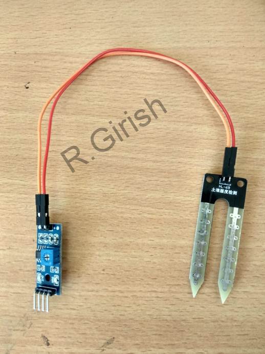
It has 4 + 2 pins, 2 pins for electrode connection and rest of the 4 pins are Vcc, GND, digital output and analog output. We are going to use only the analog output pin for sensing soil moisture.
Since we are not using digital output pin, we will not be using on-board trimmer resistor to calibrate the sensor.
Now, that concludes the soil moisture sensor.
Schematic diagram:
The circuit is kept fairly simple and beginner friendly. The schematic is divided into two parts of the same project to reduce confusion while duplicating the project.
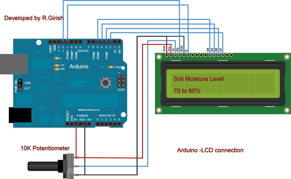
The above schematic is the LCD to arduino wiring. A 10K potentiometer is provided to adjust the contrast of the LCD display.
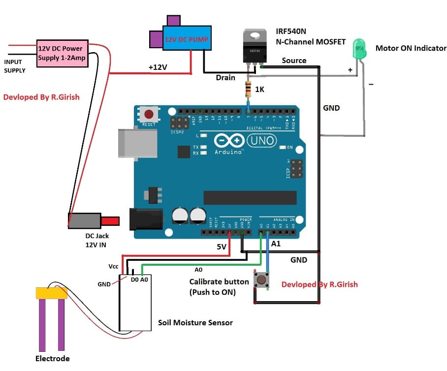
Here is the rest of the schematic consisting of soil moisture sensor, 12V DC pump, a calibrate push button and 12V (1 - 2 amp) power supply. Please use a power supply at least greater than 500mA of 12V DC pump’s current rating.
The MOSFET IRF540N (or any equivalent N-channel) is used instead of BJTs to improve the overall power efficiency of the system.
The pump will water you small garden, make sure you always have adequate amount of water is available.
Program Code:
//-------------Program Developed By R.Girish-------------//
#include <LiquidCrystal.h>
LiquidCrystal lcd(12, 11, 5, 4, 3, 2);
int Time = 5; // Set time in minutes
int threshold = 30; // set threshold in percentage: 80,70,60,50,40,30,20 only.
int i, x, y, z;
int start = 0;
int calibrateValue = 0;
const int calibrateBTN = A1;
const int input = A0;
const int motor = 7;
boolean calibration = false;
boolean rescue = false;
void setup()
{
Serial.begin(9600);
pinMode(input, INPUT);
pinMode(calibrateBTN, INPUT);
pinMode(motor, OUTPUT);
digitalWrite(calibrateBTN, HIGH);
lcd.begin(16, 2);
lcd.setCursor(0, 0);
lcd.print("Pour water and");
lcd.setCursor(0, 1);
lcd.print("press calibrate");
while (!calibration)
{
if (digitalRead(calibrateBTN) == LOW)
{
calibrateValue = analogRead(input);
x = (1023 - calibrateValue) / 10;
Serial.print("Difference = ");
Serial.println(x);
Serial.print("Calibration Value = ");
Serial.println(calibrateValue);
delay(500);
lcd.clear();
lcd.setCursor(0, 0);
lcd.print("Calibration done");
lcd.setCursor(0, 1);
lcd.print("successfully !!!");
calibration = true;
delay(2000);
}
}
}
void loop()
{
int sensorValue = analogRead(input); // Read once only
start = 0;
lcd.clear();
lcd.setCursor(0, 0);
lcd.print("Soil Moisture");
if (sensorValue <= calibrateValue)
{
lcd.setCursor(0, 1);
lcd.print("Level: 100%");
}
else if (sensorValue <= calibrateValue + x)
{
lcd.setCursor(0, 1);
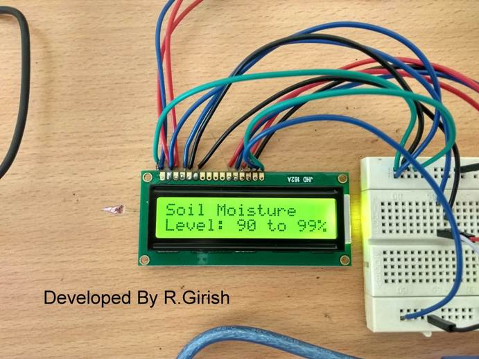
lcd.print("Level: 90 to 99%");
}
else if (sensorValue <= calibrateValue + 2 * x)
{
lcd.setCursor(0, 1);
lcd.print("Level: 80 to 90%");
start = 80;
}
else if (sensorValue <= calibrateValue + 3 * x)
{
lcd.setCursor(0, 1);
lcd.print("Level: 70 to 80%");
start = 70;
}
else if (sensorValue <= calibrateValue + 4 * x)
{
lcd.setCursor(0, 1);
lcd.print("Level: 60 to 70%");
start = 60;
}
else if (sensorValue <= calibrateValue + 5 * x)
{
lcd.setCursor(0, 1);
lcd.print("Level: 50 to 60%");
start = 50;
}
else if (sensorValue <= calibrateValue + 6 * x)
{
lcd.setCursor(0, 1);
lcd.print("Level: 40 to 50%");
start = 40;
}
else if (sensorValue <= calibrateValue + 7 * x)
{
lcd.setCursor(0, 1);
lcd.print("Level: 30 to 40%");
start = 30;
}
else if (sensorValue <= calibrateValue + 8 * x)
{
lcd.setCursor(0, 1);
lcd.print("Level: 20 to 30%");
start = 20;
}
else if (sensorValue <= calibrateValue + 9 * x)
{
lcd.setCursor(0, 1);
lcd.print("Level: 10 to 20%");
start = 10;
}
else
{
lcd.setCursor(0, 1);
lcd.print("Level: < 10%");
rescue = true;
}
if (start == threshold || rescue)
{
y = Time;
digitalWrite(motor, HIGH);
Time = Time * 60;
z = Time;
for (i = 0; i < Time; i++)
{
z--;
delay(1000);
lcd.clear();
lcd.setCursor(0, 0);
lcd.print("PUMP IS ON, WILL");
lcd.setCursor(0, 1);
lcd.print("TURN OFF IN:");
lcd.print(z);
}
Time = y;
rescue = false;
digitalWrite(motor, LOW);
}
delay(1000);
}
//-------------Program Developed By R.Girish-------------//
How to calibrate this automatic irrigation system:
• With completed hardware, insert the electrode on soil, somewhere at the path of water flow.
• Now change the two values in the program 1) The amount of time will take to water all the plants (in minutes). 2) Threshold level below which the arduino triggers the pump. You can set the percentage values 80, 70, 60, 50, 40, 30, 20 only.
int Time = 5; // Set time in minutes
int threshold = 30; // set threshold in percentage 80, 70, 60, 50, 40, 30, 20 only.
Change the values in the program.
• Upload the code to arduino and power the circuit. It will display “pour water and press calibrate”. Now you have to manually water your garden to sufficient level.
• After watering the garden, press the calibrate button. This will determine the conduction of electricity in fully moisture soil and snap shot the reference value.
• Now the system is ready to serve your small garden. Please try to add a power backup for this project. When the power fails the reference calibrated value will be wiped out of memory and you will have to calibrate the system again.
Author’s prototype:
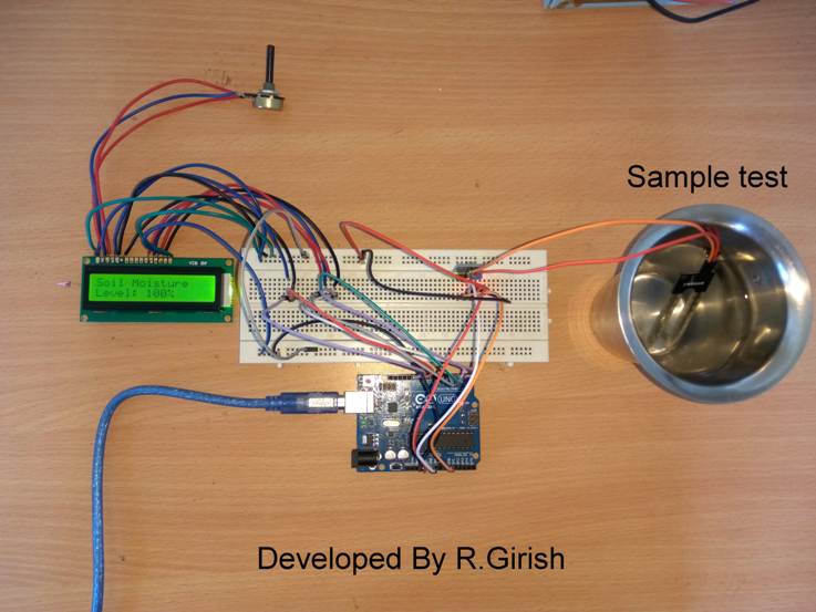
Indication of soil moisture level:
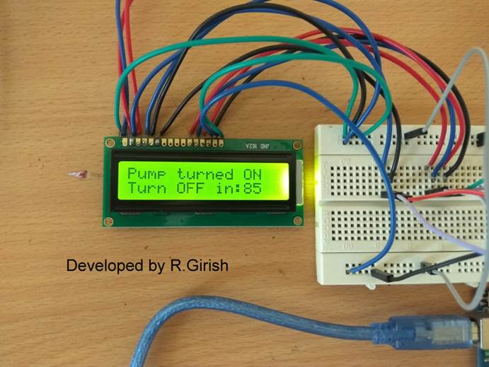
Once the pump is turned ON, it will display remaining time to turn off (in seconds).


Comments
Ok, Swagatam, writing here!
Swagatam, hello.
How are you, how are your health, how are your loved ones?
You helped me somehow – for FREE! You help everyone for free, you have a kind heart, thank you very much!
I have a suggestion! I am doing several projects.
The Smart Irrigation project is almost ready, I made two options, based on the Siemens Logo 8 controller and a multi-level soil moisture sensor on the FC-28 relay module. https://drive.google.com/file/d/1sdRwCyhOuoXGOuvZODJJpTm_N-n0EFMW/view?usp=sharing – here is a full description and explanations.
https://accentsjournals.org/PaperDirectory/Journal/IJATEE/2022/3/10.pdf
There are several similar articles.
I have already written to them, asked them a couple of questions – I hope they will answer.
That is, we need specialists who know soils and agricultural technologies. In Kazakhstan, mainly specialists in grain, cotton, potatoes…. But there are very few specialists in vegetables and greens. But it seems that I found a good agronomist with extensive experience!
Your article “Automatic Irrigation Circuit using Arduino” is a great job, just what we need! You can set percentage values!)))
– Here we need to use a digital output, probably an optocoupler with a relay, to introduce into the existing radio relay system. That is, when the value has been reached, for example, 40%, then the MLSMS sensor does not meet the request of the controller! If it is above 40%, then MLSMS sends a signal that the humidity is still normal!
If you’ve read two irrigation options:
– 1 option – there are at least 10 electrodes. Can be made on one relay module + one multi-pole switch per electrodes.
– Option 2 is less consumable, i.e. 1 electrode for root up to 0.4 m and 2 electrodes for root up to 1 m.
There are a bit of problems with finances, my projects have stopped, now I am studying freelance platforms. All these small projects are part of one large project Dala Complex, with an approximate cost of $300,000. You can earn money now.
You send me your e-mail (saudabaev@gmail.com).
Thank you so much Dan, for your kind words! I am glad you found my suggestions helpful.
I wish you all the best for your irrigation project.
I hope someone in this forum will take interest in your project and help you to accomplish it…
My email is
homemadecircuits
@gmail.com
can u make one using arduino nano
Hallo sir
I need to control an irrigation pump with three different solenoids
Each time the pump is ON the relevant solenoid valve must be ON and a message to indicate the same.
Hello Francis, code customization is a premium offer from us, presently we are charging Rs.10/- per line of customized code.
Hello sir, i need help regarding a power supply, i was trying to reuse an old ups transformer and was able to change ac to dc but the problem is its voltage fluctuates a lot according to input voltage and here in our area voltage fluctuation is a common problen,eg if the jnput voltage is 180v it supplies 8v DC and if inpur voltage is 250v it supplies 16v dc, what i need is a constant 12v output to drive some 20w leds, is it possible to get a constant output with such fluctuating input voltage
Hello Ishaan,
you can use any suitable voltage regulator IC for correcting the issue, such as this, or any similar
https://www.homemade-circuits.com/2013/04/12v-5-amp-fixed-voltage-regulator-ic.html