In this post I have explained about a unique 8x overunity circuit quite resembling a joule thief design which was created by one of the noted researcher Professor Steven E. Jones while experimenting with a simple overunity concept.
8x more Output from a Simple Joule Thief Circuit
While developing this overunity circuit he was amazed to see an 8 fold or 8x improvement in the power output, which simply indicated an 8 times more output being produced by his circuit, compared to the input supply power.
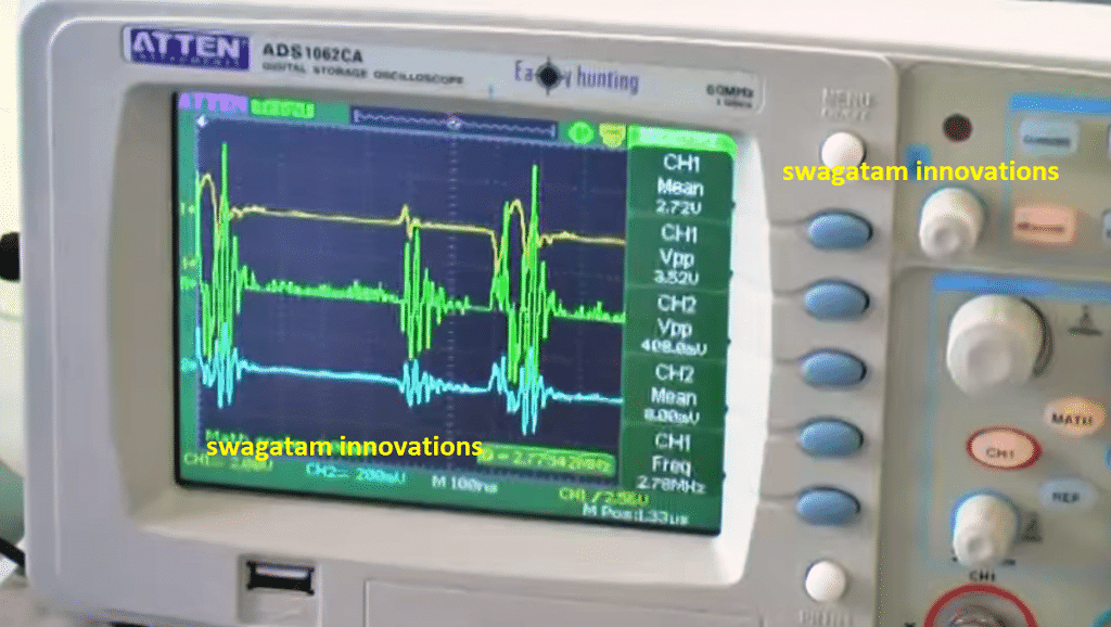
The results were distinctly evident on the oscilloscope screen which he used to verify the test results.
Mr. Steven E. Jones is an American physicist who particularly became popular for his intense research on muon-catalyzed fusion
While trying to develop a simple overunity theory he could discover this unique 8x overunity effect in his special joule thief circuit, using the advanced Tektronix oscilloscope, which made his finding look even more credible.
When asked from where the 8x free energy was coming from, professor said "I don't know where the energy is coming from, but it's coming from somewhere," and he himself seemed interested in solving it through other researchers.
During the course of the experiment, to be precisely sure about the working ability of the circuit, he kept it running overnight for 9 hours. In his prototype an LED was used as the load and a AAA cell, as the power supply.
The results were undoubtedly confirmed when he found that even after nine hours of continuous operation, the LED continued to remain illuminated brightly, yet the charge in the cell had hardly depleted. Without his circuit the cell would have easily gotten empty and the LED extinguished long before.
Although we are discussing just a fraction of milliwatts here, it's a good start and enough to prove the a substantial 8x overunity.
Circuit Diagram
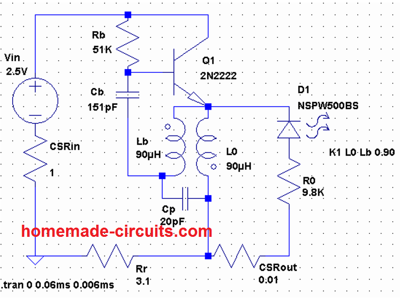
The circuit designed by Steve can be seen in the above figure, which is a modified variant of a joule thief circuit based on "blocking oscillator" principle.
In this mode, an LC network can be seen operating with the base of the BJT which you usually won't find in regular blocking oscillator designs. Professor Steven names this stage as the "boost resonator" since this stage resonates at a particular frequency and also becomes responsible for boosting the output and generating the overunity effect.
According to Mr. Steve, he could also develop a method of fine-tuning the efficiency of the circuit to a level where the input consumption virtually reaches to almost nothing.
He further revealed that the crucial element of the circuit was the inductor in the form of a torroid, specially devised by him. Although the construction of this torroidal inductor is easy, and could be hand wound, it lets you witness some amazing results.
In his design the following parts were used
Rb = 2k, 1/4 watt
Ro = 9.8k,
Rr = 3.1k,
T1 = MPS2222
Cb = 151pF,
D = LED red,
Power supply: 2V DC from a couple of rechargeable AA cells.
Both CSR = 1 ohm 1/4 watt (current sensing resistors)
Making the Inductor Coil
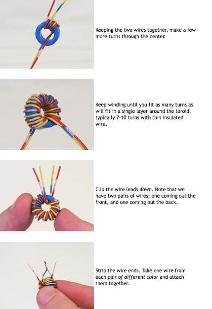
The inductor was constructed with the following details:
L-B, L-O = 9 turns using bifilar winding
Core = Torroid 1"OD, 1/2"ID, 7/16" tall
Inductance value: approximately 90uH each
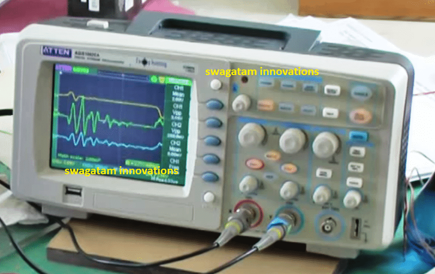
Practical Test Results
Here's the original voice transcript of professor Steven, illustrating the test results on his state-of-the-art tektronix oscilloscope.
"Basically, the power is coming from two AA rechargeable cells and little 1 ohms resistors in series with the battery, so I measure the input voltage and the input current, the voltage drop across the 1 ohm resistor and that gives me the input power, multiplying the input voltage times the input current, I get the instantaneous power that’s actually the green trace here, the yellow trace being the input voltage, the blue is the current, and the green is the output. The frequency is around 2.8MHz......"
Proof of 8X Overunity
The above outstanding research by Dr. Steven, finally proves that overunity is actually possible through some means even if it remains mysteriously untraceable.


Questions & Answers
Hi.
I see there is simulation software scheme?
Perhaps in LTSpice?
What simulation says ?
Hey, yes I have a circuit simulation page, but not LTspice, I did not simulate the above circuit yet, but you can do it below if you want:
https://www.homemade-circuits.com/simulator/circuitjs.html
Hello,
I built this circuit and with 2.2ohms on each end (input and output). Then measured voltage across the resistors (for current) and voltage across input and output *light diode and resistor”, and to my surprise got 2.75 volts input 16.6mW, and output 4.8volts (on oscope) with 18.3mW output. just a bit more, no 8X. I’ll play more with it.
Hi Ken. I had found this circuit years ago and managed to dig up a copy. It was from 13 yrs ago and built by a fellow in Romania if I remember correctly. Anyways I will paste in the link in this message. What was interesting to me is that it is a similar circuit yet simpler than the Steven Jones’ circuit, I think, and well what caught my attention was that he also claimed, wouldn’t you know it, 8 times output over input. WTH eh??
https://www.homemade-circuits.com/wp-content/uploads/2026/06/Overunity-Joule-Thief.pdf
Oh my gosh!
I did this simple circuit and got a ferrite core, did it bifilar about 80 turns or so.
Input was 1.55V (new battery) and used BAT81 ultra fast diode, with 6.8mF too.
The output was 3.74VDC. Now connecting a load to this output at 19.5mW (680ohm load), the input drew 5.3mA or 8mW input. The LED is green and bright also. I assessed this at 243% over unity. WOW. More testing I’ll be doing. Without a load it drew 5.9mW.
update, used RMS readings on the output, input fixed with 2.9VDC power supply. still 18.9mW on input but 21.9mW RMS on output. Double checked this 3-4 times. Very odd. I’m a retired Electrical Engineer worked with Electromagnetic Environmental Effects on Navy Ships. Always looking for overunity, free energy. This one stumps me most.
Your results are fascinating. Yes you didn’t get the claimed 8x power increase but so what, you’ve demonstrated overunity. That’s no small achievement! I have built various joule thief type configurations over the years and while they were fun I never got more power out than what went in. So I congratulate you on your achievement. I too will go at it again but in the configuration above this time.
Have you experimented more since then? I wonder how a person could ramp up this voltage and amps to something more practical? I don’t know the limits of the components such as how high a volts and amps can we get in a transistor? Well good luck and thank you for posting that good news.
Thanks for your efforts to test this circuit, even that small increase in the output power is surprising, because according to the standard rules of thermodynamics, any form of overunity is impossible from any electrical system on this planet…
This man should not call himself a professor if he does not know where the 8 x double “energy ” comes from, because it does not generate 8 X energy but an 8 x higher voltage with an 8 x lower current … and a slightly lower power if you put in it (he never heard of copper losses and efficiency.??)
Im quite sure he knows exactly what hes doing since it should be fairly obvious to a professor why the values he calculated are wrong. Since there is a significant AC component with voltage and current not in phase, you can’t just multiply them to get the real power. If he added a smoothing capacitor and a linear load, he would have measured and calculated an efficiency below 1 and he knows that.
Hi,
I want your help to replicate the first circuit here:
https://web.archive.org/web/20061110100538/http://www.overunity.com/index.php/topic,1310.0.html
Please email me. I can pay for a video of the replication of the experience
I’ve read all the comments here and NO ONE clearly stated that they actually built this circuit and ran it. Has anyone tried this circuit? Why dont you limit posts to directly relevant activity? Also I dont believe those posting with questions regarding violations of the laws of thermodynamics, etc., are appropriate here. I believe everyone working on these types of devices knows that this goes against mainstream science which has questionable motives. Censorship is alive and well these days.
I have built and powered up this JT8, as I like to call it, and so far it isnt running properly. I am now switching component values between what is shown on the schematic and what is shown on the parts list.
I see several discrepancies in the assembly and the testing as per the instructions attached but there isnt much value in discussing problems with anyone who hasnt built and tried it yet.
I have built this concept several times, with the aim of getting a higher voltage,
This works, and is called a “Youles thief ” .. the output voltage is higher, but the amperage lower.
Subtract the copper losses here, and the output power is always a little bit lower.
So … nothing free … even a small loss ..
As explained in the article, the concept has already been thoroughly tested by a renowned researcher. The oscilloscope results are also shown in the above article.
So that somehow proves that the circuit is a tested design.
Resonant circuits can easily multiply power. A series resonant circuit will have equal and opposite voltages in the capacitor and inductor and these voltages will be Q times higher than the input signal voltage.
Here Q is the quality factor of the circuit defined as Q = Xc/R = Xl/R, where Xl and Xc are the inductive and capacitive reactance and R is the Resistance, all in Ohms.
In a tuned circuit, any resonant input greater than circuit dissipation will cause a resonant rise In energy as defined by Q. So for example with an inductor Xl will increase with frequency. Xl = 2πf L, where f is frequency, in Hz and L is inductance in Henries.
At resonance Xc and Xl are equal and opposite and cancel. So only On if resistance will oppose current flow.
Do you know where I can get a full set of blueprints for this? I have two children under 6 and I am a single mom that wants to be prepared for anything. Is this something that a “laywoman” could build? I have heard that it can be very simple but I would need a full tools & material list and a full set of instructions. I would be looking to power my house in the event of an EMP or other such attack. Thanks so much for your post.
Samantha, many of us share your exact interest.
But even if you had this exact device running successfully at home on your kitchen table it would still be a lot more work and expense to scale it up to run your house for lighting, heating, air conditioning, etc. and your car. Some people would also like to sell electricity back to the electric company with a grid tie like my son does with his Tesla installed solar power system.
At one of John Bedini’s annual conferences in 2014 I asked one of his people what I need to do to run my house or car and he said “just get a bunch of solar panels”. So, while several of these “free energy” devices may work overunity they still cost money to implement AFTER you figure out which ones work and which ones dont. My search started around 1985.
Also, you would need to shield this device from an EMP strike because without shielding it will be damaged. And many of the electrical devices in your house would be damaged by an EMP so you wouldnt need electricity to run them anymore if they arent protected. Shielding everything in your house would not be easy to do.
Please keep up your search.
Thank you for you interesting question. I don’t think the above circuit can be built and tested by a laywoman since it needs a great deal of expertise in the field of electronics.
Any chance you know where one could purchase one?
Sorry, this circuit is not available ready made. Possibly, you can hire an online engineer to build one for you and then you can purchase it from him.
The parts shown on the schematic do not match the parts list. Please clarify, Swagatam, and thank you for your work.
resistors on schematic; 0.01 ohm, 1 ohm, 3.1k, 9.8k and 51k, caps; 20pf and 151pf. I believe, from reading the text, that the 0.01 ohm should be 1 ohm.
resistors on parts list; 2k, 9.8k, 3.1k, caps; 151pf.
Thank you Richard,
Actually the above article was acquired from an external source a long time ago, so I do not remember why there’s a difference between the parts list and the diagram. I would suggest you first try the parts which is shown in the diagram, and keep experimenting until the most efficient outcome is achieved.
Here’s just a further thought about joule thieves, in relation to Tesla’s patent on the bifilar coil, aka pancake:
Running a bifilar in parallel has no special effect on the capacitance. But in series it has a high capacitance: half of the entire voltage drop is capacitive charge separation. Now if you pulse it parallel and then let it collapse serially, there is suddenly a capacitive charge present that cannot origin from the pulse. This makes the bifilar coil a variable capacitor, no moving parts and controlled electronically.
Furthermore, if the pulse is anti-parallel, then there is no impedance, so the coils are loaded almost immediately. (An additional monofilar coil before ground can further throw energy back into the circuit, rather than to just dump it to ground).
So the pulse (maybe 1% duty cycle square wave) would go in anti-parallel, but a (real) capacitor at the end of one winding allows for the bifilar coil to switch to serial ringing, as soon as the pulse stops.The same may be true for asymmetric bifilar coils like the one in the joule thief.
That being said, this isn’t exactly verified science. However, there is something about capacitors that’s really mind boggling: alter the capacitance of an uncharged 2-plate capacitor: increase the distance, it gets charged! But as it’s charged, plates attract each-other physically, hence you need energy to separate them – law of energy conservation saved – for now. Now discharge it and move plates closer, it gets charged again, but this time the attraction will help your physical motion, which violates the said law from my point of view, and could explain several phenomena. Everybody with two pieces of aluminum foil and a volt meter can do this experiment. Try: Book – aluminum – kitchen wrap – aluminum – book sandwich, then squeeze it and watch the voltage.
Hi Swagatam,
I just found this page and I’m really impressed. I did some research in similar fields too, but struggled in finding people capable of comprehending and/or paying attention.
I stumbled upon an apparent loophole in the Lenz law, that’s logical, yet violates thermodynamics. Now I’m searching for an open-minded, technically competent person who’s willing to take a look at it, and whether he sees a flaw. I condensed the theory to two 2 minutes long videos you can find on my profile on twitter:
https://twitter.com/DieterMarfurt/status/1600999478928232448
Thank you very much.
Thank You Dieter,
I appreciate your question.
However, I don’t think I have sufficient knowledge in the field of thermodynamics or to analyze Lenz’s law, so I may not be competent enough to answer your questions.
If possible, in my free time I will try to investigate the issue and let you know.
Thank you very much, that would be great!
To all:
It isn’t that hard to understand, actually. Once you realize that the essence of the Lenz law is: a coil repels an increasing magnetic field-strength and attracts a decreasing field-strength (but only if we let the current flow) and therefor becomes a brake to the rotor, which accounts for the losses that keep conventional generators below 100% , then it’s just one further thought to imagine a magnet that’s strong at a distance and weak when close by (to the coil) – this reversal of magnetic behavior also reverses the brake effect into an acceleration effect. The video shows an implementation approach of such a special magnet.
what is the practical use of this circuit and what happens if you raise the 2.8 MHz to 5 GHz does it increase the voltage out
Hello- Can’t say for sure but the 2.8 mhz is probably the resonate frequency of the coil. Any adjustments in frequency up or down would effect the results negatively.
Everything is very open with a precise description of the challenges. It was truly informative. Your website is useful. Thank you for sharing!
I have found another way of creating over unity with resonant circuits. In a series resonant circuit the input current flows equally through Land C. But , at resonance the voltage across L and C are about equal and opposite and much higher than the input signal voltage. Some researchers claim that this voltage is Q times higher where Q is the quality factor of the tuned circuit at the resonant frequency. Since power is current times voltage the power in either L or C will be higher. If L is bifiler power can be easily tapped from L.. Alternatively in a parallel tuned circuit, the signal voltage is the same in L and C but the currents will be opposite and equal and much higher than the signal current.
Tesla also said the same thing in free Electric power so does this mean that were are re discovering Tesla’s theory on resonant frequency and what happens if you raise the frequency to 5 GHz ?
Sounds great! Thanks a lot for this valuable information.
Looking at the pictures, i couldn’t identify which model of Tektronix scope was being used–was it another vendor instead?
Electric power can be easily magnified in resonating circuits, aided by the resonate rise and the quality factor, Q of the circuit.
In a series resonant circuit the voltages in the inductor will be equal and opposite that of the capacitor. And, each of these voltages will be Q times the input signal voltage.
In a parallel resonate circuit, the current in the inductor and and capacitor will be equal and opposite and Q times the signal current.
In an inductor, Q = Xl/R where Xl is the inductor reactance in Ohms, and R is the Inductor resistance in Ohms. Xl reactance is frequency dependent, Xl = 2πfL, where f is frequency in Hz and L is inductance in Henries.
Anyone heard of the conservation of energy or thermodynamics. You cannot create more energy that is actually usuable than you put in. Whatever is happening in these circuits is either piking up eletromagnetic energy from ambient signals of which we are surrounded, bluetooth, wifi, DAB, TV etc.
Or its wishful thinking or bad understanding of electronic principles and calculations.
While he said the AAA cell get depleted much slower – it still gets depleted and hence is below 100% efficiency. However there are several loopholes in those laws, they are not absolute. Like:
cavity implosion in ultrasound
disassociation of diatomics on catalytic surfaces
PN junction electron flow
low energy nuclear reaction lenr
static charge theft by variable capacitors (joule thieves do that too)
anti lenz field postulate
IDK how much you know about electro-magnetics, but here’s some food for thought:
https://twitter.com/DieterMarfurt/status/1600999478928232448
The supply batteries running down is not an indication of less than 100% efficiency.
If the output power to the LED was rather fed back, in a proper manner, to recharge the supply batteries, then we may suspect less than 100% efficiency if the batteries eventually ran down. I would suggest using mechanical latching relays to periodically switch the supply with the load batteries (replacing the LED) or capacitors instead because of their low contact resistance and as latching relays they draw no power except when switching.
This would preclude the need for the oscilloscope and would be more of a “proof is in the pudding” approach.
Do the batteries continue to increase in charge or do they decrease ?
Yes, that’s what I will explained at technical school and university. But let’s remember Nikola Tesla and the other “dissidents”! I have also experienced inexplicable phenomena. I worked for years in research laboratories, quantum physics is different in many areas!
Thank you for your useful feedback, appreciate it very much!
Hello Swagatam,
It seems that wrapping the wire on a toroid causes the magnetic and electric fields to rotate around the toroid causing a vortex, obviously pulling in extra energies. this is similar to Tesla’s Toroid for distribution of energy US patent US381970A. people do not know he got one over on the patent office. also Iron and other materials amplify current referring to electrical storms that cause transformers output to shoot through the roof and blow up. Rotating vortex does pull in extra energy, the larger the vortex the more energy pulled in.
also a reference; why does it take 300 watts to start a motor, run for a few minutes then shut off. it started within 30 seconds to a minute the motor will draw only 100 to 150 wats of power to start. WHY ? Vortex was created and does not immediately dissipate. all these are facts.
PS. love your web site and your mission.
Thank you Donald, you may be correct. I appreciate the valuable information that you have shared with all of us here.
Hi Swagatam;
My aim is to make mini heater input is 3 or 5 V reduced from 9 V and I need the current as low as possible. I have the chrome resistant wire of diameters 0.20 and 0.4 mm. Heat will be about under 30 degree C. Is it possible to use this joule thief circuit. Thanks
Hello Suat. It depends on the fluid for heating – a gas or a liquid or a powder or a pulpa\emulsia or else. If were you gave necessary or desired total power of your heater in whatts=joul per second – it would be grate. just there are a Law of Nature – if the dissipated from “crome resiatant” power more than given from the power source – the heat will be wery less than 30 Celsius degree despite a largest possible to the 9V supply’s current it is ONLY YOUR TROUBLE!!!!!!! you must know the rate – how many thermal energy is necessary to the with the heater process – to – how many energy can give the power supply. Without these data nobody can help you distantly.
Or to made a few tests – as you understand – with use of a clip to connect your crome resistant wire without cut off it – until you find out desired results.
I agree ! There is no more correct method for measuring thermal energy!
Thanks an Igor I need to try your advises and to understand details.
Hi Suat, yes you can try the joule thief concept for your application. More info can be found in the following post:
3 Best Joule Thief Circuits
which part (I think transistor would be) may be exposed to overheating. What about the idea to include 555 timer circuit to run the circuit by pausing in short periods to eliminate the overheating. Or should be enough to use proper resistant. Many thanks again.P.S.: Meanwhile I preferred the circuit which run the 12 V small DC motor with the diode rectifier
I think 30 degrees Celsius is very less heat, and this will not cause any heating on the transistors. I guess even nichrome wire is not needed for so little heat, you can simply use any wire-would resistor for this.