In this post I have explained about stepper motor. We will be exploring what stepper motor is, its fundamental working mechanism, types of stepper motor, stepping modes, and lastly its advantages and disadvantages.
What is stepper motor?
Stepper motor is brushless motor; its rotating shaft (rotor) completes one rotation with a determined number of steps. Due to the stepped nature of rotation it gains it name as stepper motor.
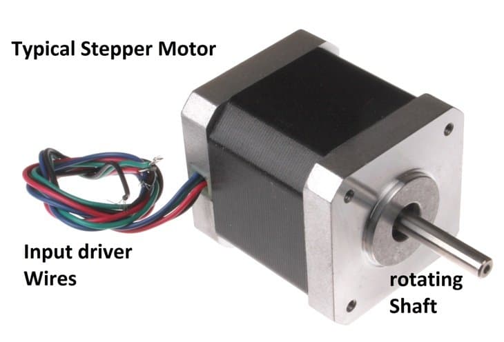
Stepper motor provides precise control over rotational angle and speed. It is an open-loop design, which means no feedback mechanism is implemented for tracking the rotation.
It can vary its speed, change rotating direction and lock into one position instantly. The number of steps is determined by number of teeth present in the rotor. For example: if a stepper motor consists of 200 teeth then,
360(degree)/200(no of teeth) = 1.8 degree
So, the each step will be 1.8 degree. Stepper motors are controlled by microcontrollers and driver circuit. It is widely used in laser printers, 3D printers, optical drives, robotics etc.
Fundamental working mechanism:
A stepper motor may consist of several numbers of poles wound with insulated copper wire called stator or non-moving part of the motor. The moving part of the motor is called as rotor, which consists of several numbers of teeth.
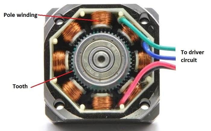
When one pole is energized, the nearest teeth will gets align with that energized pole and other tooth on rotor will slightly offset or unaligned with other un-energized poles.
The next pole will gets energized and previous pole will get de-energized, now the unaligned poles will gets align with currently energized pole, this make one single step.
The next pole gets energised and previous pole gets de-energized, this make another step and this cycle continues several times to make one full rotation.
Here is another very simple example how stepper motor functions:
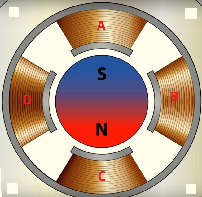
Generally the rotor teeth are magnets arranged in alternating north and South Pole fashion. Like poles repel and unlike pole attract, now pole winding ‘A’ is energized and assume energized pole as North Pole and rotor as South Pole, this attract south pole of rotor towards pole ‘A’ stator as shown in image.
Now pole A is de-energized and pole ‘B’ is energized, now the south pole of rotor will align with pole ‘B’. Similar pole ‘C’ and pole ‘D’ will energize and de-energize in same fashion to complete one rotation.
By now you would understand how a stepper motor working mechanism.
Types of stepper motor:
There are three types of stepper motor:
• Permanent magnet stepper
• Variable reluctant stepper
• Hybrid synchronous stepper
Permanent Magnet stepper:
Permanent magnet stepper motors use permanent magnet teeth in rotor which are arranged in alternating pole fashion (North-South-North-South……), this provide greater torque.
Variable reluctant stepper:
Variable reluctant stepper uses soft iron material as rotor with several number of teeth and operate based on the principle that minimum reluctant occur at minimum gap, which means the nearest teeth of rotor gets attracted towards the pole when it is energized, like a metal gets attract towards a magnet.
Hybrid synchronous stepper:
In hybrid stepper motor both the above mentioned method is combined to get maximum torque. This is the most common type of stepper motor and also expensive method.
Stepping modes:
There are 3 types of stepping modes
• Full stepping mode
• Half-stepping mode
• Micro stepping mode
Full Stepping mode:
In full step mode can be understood by the following example: if a stepper motor has 200 teeth then, one full step is 1.8 degree (which is given at beginning of the article) it won’t rotate less or more than 1.8 degree.
Full step is further classified into two types:
• Single phase mode
• Two phase mode
In both the phase mode, the rotor takes one full step, the basic difference between these two are, single mode gives less torque and two phase mode gives more torque.
• Single Phase mode:
In single phase mode only one phase (a group of winding/pole) is energized at a given time, it is the least energy consuming method but it also gives less torque.
• Two Phase mode:
In two phase mode, two phase (two group of winding/pole) is energized at a given time; it produces more torque (30% to 40%) the single phase mode.
Half stepping mode:
Half stepping mode is done for double the resolution of the motor. In half step as the name suggest it takes half of the one full step, instead of full 1.8 degree, half step takes 0.9 degree.
Half step is achieved by changing single phase mode and double phase mode alternatively. It reduces stress on mechanical parts and increase smoothness in rotation. Half step reduces torque by around 15%. But torque can be increased by increasing the current applied to the motor.
Micro stepping:
Micro stepping is done for the smoothest rotation. One full step is divided up to 256 steps. For micro stepping it need special microstep controller. Its torque is deduces by around 30%.
The drivers need to input sinusoidal wave for fluid rotation. The drivers give two sinusoidal input with 90 degree phase out.
It gives best control over rotation and reduces mechanical stress significantly and reduces the operational noise.
The main advantages and disadvantages of stepper motor can be learned with the following points:
Advantages:
• Best control over angular rotation.
• High torque at slow speed.
• Instant change in rotational direction.
• Minimal mechanical construction.
Disadvantages:
• Power is consumed even during no rotation; this done for locking the rotor to fixed position.
• No feedback mechanism is there to correct against rotational errors and to track current position.
• It needs complicated driver circuit.
• Torque is reduced at higher speed.
• It is not easy to control the motor at higher speed.

Questions & Answers
Dear Swagatam,
Good afternoon,
In my latest project, I use two ULN 2003 APG IC’s to control two 28BYJ-48 stepper motors. Both motors operate normally when I use thick jumper wires. When I use thin jumper wires, only one motor shaft rotates. The second stepper motor shaft does not rotate. It vibrates. The second stepper motor shaft rotates, when thicker jumper wires are used. Here is the link to the video please:youtu.be/NrSTtqWNRwI?feature=shared
May I request you to please tell me the reasons for this behavior.
Thanking you for your time,
yours faithfully,
Vishwa Mukh Bharadwaj
Dear Vishwa,
As far as I believe, wire thickness cannot affect the working of servo motors unless the motor is rated to work with significant currents, even in that case only the wires would become hot, the motors would still keep rotating.
So i am not sure why you are facing this problem?
I hope you will be able to solve it soon.
Sir,
Good evening,
Thanks for your prompt reply.
yours faithfully,
Vishwa Mukh Bharadwaj
yes , can you tell me how a steper motor is wired i have two that a friend gave me ,and i was wondering if they work like a regular spinning motor
You can refer to the following post, which explains how to wire a stepper motor through an IC 555
https://www.homemade-circuits.com/driving-unipolar-stepper-motor-using-ic/
you had posted the question in the following article
https://www.homemade-circuits.com/2017/01/high-current-wireless-battery-charger.html
Sir, good morning to you. Thanks for the answer. But I am not able to find it in spite of repeated sincere surch. So sir if you kindly repost the answer here I will ever thankful to you. Regards.
Sir, Good morning to you. Unable to find a solution from any where I have turned to your website as a last resort. I need to travel cross country in car, using Google maps. The travel time sometimes last for 4-5 hours. I am using ASUS ZenFone for the purpose. I face great difficulty in charging the mobile while continuing to use Google maps for navigation. In spite of keeping the mobile connected to the adaptor charger, ultimately the mobile's battery drain out completely after about 3-4 hours. I have tried no of adopters, but none could solve my problem. The mobile get / remains fully charged when connected to 10000mAh power bank. I have opened two of the adopters and found one of them using IC MC54063AN,photo attached as (A)and other one using IC XC1530E, photo attached as (B). Please help me in modification of the circuitry to increase the charging current of these adopters. I am a 3years diploma in ECS. I will be able to follow your advice on the matter. Thanks ®ards.
Photo
Photo
Debasis, I have already answered this question which you had posted yesterday under some other post