In this post I have explained a simple food warmer lamp timer circuit for restaurants and hotels which can be used for automatically switching OFF the lamps after a predetermined time whenever the food under the lamps are idle or in the absence of an interaction under the lamps, thus saving precious electricity. The idea was requested by Mr. Mike Sunny.
Automatic Food Warmer Lamp Timer Circuit
- The heat lamp is the kind used to keep food warm in hotel restaurants, cafes etc. Most are about 400 watts
- The lamps are usually installed in parallel, with about 10 on one power track rail
- The power track rail is energized by a wall switch, with each individual lamp having its own dedicated lamp switch
- There are many type of heat lamps, like carving stations or lamps that hang from the ceiling (please see attached pic, there are many types of configs, the attached pic is the rail type, the chefs station is placed on a buffet line)
- So the chef places the dish under the heat lamp, until the waiter takes it away, or the meat is
- under the chefs station (different config but same principle; keeping an item warm)
- The lamps in their present configuration can be individually turned on, but it would be added value if they were automatic
- So a more ideal config would be for the lamp to self regulate its temp according to the temp of the food placed under it, and also be self activated by motion, or lack of motion (timed?).
- Im thinking the self activating function could be activated with motion and then a timer start a countdown (resistor cap?), so if there is no plate put under the lamp to activate the temp sensor or motion to activate a motion sensor, then after some time the lamp would go off. I guess "time" would be the "catch all" final parameter.
So there would be 3 parameters:
1. if the dish under the lamp gets too warm due to a busy service or lack of customers, the temp sensor would
regulate the lamps heat
2. someone places a dish under the lamp, motion sensor turns on lamp
3. there is no dish under the lamp and the temp under the lamp doesnt get hot enough to activate the temp sensor
so a time out function turns off the lamp
The 3rd requirement may not be necessary as the temp control function might take the lamp off line in the event
there is no dish as the metal shelf or counter, with no dish on it, (empty space) might get hot enough to activate the thermostat and take the lamp off line
So power would be saved by keeping the food at a set temp, and if not motion detected after some time, the lamp would be cut off
I have been drawing up the circuit for the Heat Lamp PIR and Thermopile tie in config but I cant
make the connection as to what I need to switch in the PIR for motion, then regulate temp with the thermopile circuit, both circuits working at the same time
For the motion part of it, Im guessing it would just be a motion sensor, with a 555 timer function (resistor / cap?) that switches in a relay or mosfet? Just something to turn on the lamp, keep it on for a preset time, then turn it off.
The challenges arrives when I get to the design part where I want at the motion circuit to work in tandem with the thermopile temp sensing circuit that cycles on/off according to the temp of the air above the air of the food, as you previsouly described . The motion sensing circuit would take priority when it times out, as I dont want the lamp cycling on and off without a plate under it.
So the chef would wake up the lamp by activating the motion detection circuit when he places a dish under it, the motion detector circuit then starts to count down, and the thermopile circuit is sensing and regulating the temp of the food. Ample time would be provided for the count down, say 5 minutes, An audible alarm could even be an option, say for ex after 5 minutes, an alarm sounds, alerting the staff that the dish has been sitting too long
Any information you could provide when you are not busy and get a break would be greatly appreciated.
My Reply:
I was wondering if an ultrasonic level detector, mounted on the lamp shade, could dectect a change
in level as the plate was placed under it. The plate would upset the "distance" that was previously
detected. that could then be fed to a opamp comparator?
they seem to be quite large; perhaps there is a smaller one
presently most heat lamps I have serviced have no capability to self regulate their heat and duty cycle they are either on all the time, or have to be manually switched off. As you know, their watt consumption is quite high, especially when you have 10 or 15 in one bank of lamps Therefore I am searching for a solution that is automatic, so the chef, waiter etc is hands free. of course they could manually turn it off, but most don't have the time for this. So the application would require that the lamp can self regulate by sensing the temp of the food under it. Once it reached, for ex. 80C, then it would cut off also, when a plate was positioned under or removed from under it. the sensor cannot be external; it must be inside the lamp due to hygienic and sales points. I think these options would greatly increase the value of the lamp.
Feedback
The delay control is not an issue, the main issue is to make the sensor understand whether the food was introduced or removed? because both these actions would cause a movement....the sensing will need to be foolproof and there should be no possibility of an opposite response from the sensor, which might cause the lamp to shut off when food was placed and light up when the food was removed.
the motion direction has to be taken into consideration and implemented with the sensors.
a dual LDR sensor such the following concept as in solar trackers must be employed which would perfectly understand whether the food was introduced or removed by the difference in light across the two LDRs
Only 2 parameters will be required. Thank you for your patience; and I do apologize for my lack of clarity
1). The lamp will turn on if it detects motion. If it is already in the ON state, and motion is detected, it wont matter as it is in the latched state and further motion will be ignored. So, if the lamp is off, due to having timed out, there needs to be a way to wake it up, and the motion sensor would do this
2.) Once the lamp is ON, it will require a count down or timer function so that after a period of time, say 5 minutes ( a variable time option would be best but for this prototype, a fixed time varible is OK) the lamp would cut off. It would not matter if food was under it or not.
This application is for the overhead heat lamps where the establishment is quite busy and the food is being taken/replaced quite rapidly by the waiter staff. A dish under a lamp for over 10 minutes would be too long, as the patron is waiting for their food.
In the case of chefs stations on a buffet line, this config is not applicable; only the temp control is applicable since on a buffet line the lamp would be on all the time
Perhaps you have been in a busy hotel restaurant and seen the chef put the dish up on the counter, with heat lamps all on. The lamps with no food under them are wasting power. So, a circuit to turn them off after a period of time, and wake them ON when they sense motion would be added value to the sale?
The latch would be broke by the time out of the cap
So the chef in the busy kitchen puts the dish up on the counter, under the heat lamp. In todays heat lamps Ive worked on, the chef must manually turn them on / off. His hands are greasy and after 1 year or so, the switches fail due to grease etc, and most chefs just leave them on all the time.
So my idea is to offer the chef a hands free heat lamp alternative where he just puts the dish on the counter and doesn't concern himself with the ON/OFF/TEMP function of the lamp; it is all automatic. Of course many more options could be added latter to increase the value of the lamp, like an audible sound after the time out has completed, and varible time selection
I think the PIR motion option for say 10 minutes max then cut off is best, especially for a high dish traffic application like a counter or table where the chef wants to get the food moved fast
As you can see there are many applications for the heat lamp, some are on the buffet line, some chef station some are kitchen counter, so the app Im looking to add value to is as in the above picture link where the food needs to be warmed, but moved fast. As of now, they are a bit low tech, just turn on, forget it and consume power when not used.
They burn up quite fast, also this is a better example, you can see the dishes on the counter, and all lamps on. say if lamp # 3 had no dish under it, but was left on, its wasting power. So a pir to sense the motion, stay on for say 5 minutes, then time out, would save power so as you can see, say if you had 10 lamps at 300 watts each x 8 hours x 6 days its a huge cost, even just changing the duty cycle of one might be a significant savings
Yes, for the counter overhead heat lamps, just need an ON/OFF duty cycle controlled by motion, no need for temp control
Yes, after thinking it over, I agree with you, I don't require the thermopile temp sensor option as it is not applicable for this heat lamp as these lamps are meant to be at the same temp at all times. I will not require that option, so it makes things simplier just to implement the motion control option only. I will try your thermopile circuit on another application like an incubator so similar idea, so I appreciate that circuit
I will need to go ahead with the motion control heat lamp circuit option as I think it has application on the counter style lamps
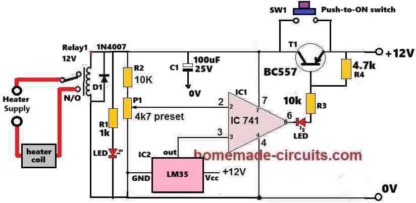
The Design
The proposed automatic food warmer lamp timer circuit for hotels and restaurants can be built using the following simple concept:

Parts List
R1 = 2M2
R2,R4.R5,R6,R7= 10K
R3= 100
P1 = 1M
C1 = 1uF/25V
C2=0.22uF
T1,T2,T3 = BC547
T4 = BC557
D1,D5 = 1N4148
D4= 6A4
D2,D3 = 1N4007
IC1 = 4060
IC2 = 4017
How the Circuit Functions
The operational sequence can be understood with the help of the following explanations:
When power is switched ON, C2 resets both the ICs which initiates the IC1 4060 timer to begin its counting process, while IC2 4017 begins with a logic high at its pin#3.
The logic high at pin#3 activates REL#2 such that the attached food warmer lamp illuminates with full brightness.
The lamp stays illuminated while IC1 counts, and as soon the first pulse from IC1 pin#3 arrives, the logic high at IC2 pin#3 jumps to its pin#2, which deactivates REL#2 and activates REL#1.
REL#1 "contacts" can be seen with a series diode D4 which instantly causes the food warmer lamp to illuminate at a 50% less illumination.
The lamp stays in this condition until the next pulse from the IC1 4060 is triggered, which forces the sequence at pin#2 of IC2 4017 to jump to pin#4.
As soon as this happens REL#1 deactivates switching OFF the lamp, while the logic high at pin#4 of IC2 jams pin#11 of IC1 and makes sure the system gets latched.
At the extreme left of the diagram we can see a PIR circuit which is specifically introduced to detect motion below the lamp.
Any time during the above explained lamp timer activation process if the PIR happens to detect a movement under the lamp, it triggers the BJT stage and forces the IC1/IC2 to reset back to their original conditions and initiate the lamp and the timer counting process.
Therefore on a busy day the PIR keeps the circuit active and the lamp switched ON while the food under the lamps undergoes a constant movement and exchange process. This allows the chef to keep the food steaming hot and at a standby position while the waiter hurries to carry them for the hungry customers. however during a less busy day, when the interaction under the lamps is lethargic, the automatic timer circuit comes into action and makes sure the food warmer lamps do not stay switched ON unnecessarily for too long, thus saving precious electricity and $.


Questions & Answers
Pls sir I need load level indicator circuit for inverter
Using LEDs or meter?
yes inductor can be also tried, but a capacitor would be much compact and easy to calculate and use, whereas implementing an inductor would require a lot more hard work, that's why I prefer a capacitor.