• Skip to main content
  • Skip to primary sidebar

Homemade Circuit Projects

Need circuit help? Post them in the comments! I've answered over 50,000!

Blog | Categories | About | Contact | Calculators-online
You are here: Home / Transmitter Circuits / Cell Phone Triggered Night Lamp Circuit
warning message: electricity is dangerous, proceed with caution
rf detector

Cell Phone Triggered Night Lamp Circuit

Last Updated on June 20, 2019 by Swagatam 7 Comments

Feeling difficult to grope for a light switch in deep sleep when someone calls you at night? Then may be this cellphone triggered RF night lamp circuit can solve your problem....This is a very simple basic circuit and is easy to construct compared to other online available circuits which switches on a relay when it detects a cellphone RF signal.

Table of Contents
  • USES:
  • CIRCUIT DESCRIPTION:
  • INSTALLATION SUGGESTIONS:
  • Circuit Diagram

USES:

This circuit can be fixed in your bedroom and switch it on during night times so that when it detects an RF signal from cellphone, it switches on a relay and hence easily enabling the user to reach his mobile which might be kept away from bed and also enables him to easily write down any important information given by the caller.

CIRCUIT DESCRIPTION:

This circuit detects any RF signal within its vicinity (8-10 metres). Place it near the switch board and connect the relay contacts to the light bulb and it aids you to reach your mobile during nights......

Here instead of using a single transistor(like 2N4403), we used a darlington pair of BC516 transistor and hence the sensitivity of the circuit is increased to the maximum extent......

You can use a 30 inch long single cored wire as antenna if telescopic antenna is not available.

A high value capacitor C2 is added to the relay contacts which makes sure that the relay is not triggered immediately due to some false RF signal but only after making sure the signal is genuine (i.e., the RF signal should be present for few seconds before firing the relay) .

When power is applied to the relay contacts, initially, the capacitor is filled up with the charge and hence serving as a time delay. If the power is applied due to false RF signal, then the capacitor charges and discharges preventing the relay from triggering.

INSTALLATION SUGGESTIONS:

Solder the components on a general purpose PCB and keep the entire assembly in a plastic casing. Make sure to solder the relay on small PCB piece and keep the relay away from the circuit in the same plastic casing (as it switches mains AC). Connect the circuit to mains power and light bulb carefully and stick it above the switch board. And the antenna wire should come out from the casing.

AND INCLUDE A SWITCH FOR MAINS POWER SUPPLY SO YOU CAN SWITCH THE CIRCUIT ON DURING NIGHT TIMES. The circuit can work on any voltage from 6-12V. But make sure to use a relay that matches the voltage of power supply and the relay contacts current rating must match the bulb’s current rating.

Written and Submitted by: SS kopparthy 

Circuit Diagram
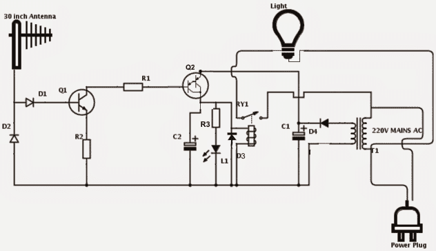
PARTS LIST:

  • Q1 - 2N4401,
  • R1 – 10K,
  • R2 – 2.2K,
  • R3 – 470ohms,
  • D1, D2 – 1N34 germanium diodes,
  • Q2 – BC516 darlington pair,
  • L1 – GREEN LED,
  • D3, D4 – 1N4007,
  • C1 – 1000uf, 25V,
  • C2 – 3300uf, 25V,
  • RY1 – (as per DC voltage rating),
  • T1 – 12V, 500ma transformer ,
  • Antenna - 30 inch long Telescopic antenna or 30 inch long single cored wire.

You'll also like:

  • 1.  Laser Communicator Circuit – Send, Receive Data with Laser
  • 2.  Electronic Door for Pets Circuit – Opens when Pet Nears the Door
  • 3.  Simple Cellphone Jammer Circuit
  • 4.  RFID Reader Circuit using Arduino
  • 5.  Transmitter Receiver Circuit for 80-meter Ham Radio
  • 6.  10 Simple FM Transmitter Circuit Diagrams Explained

Filed Under: Transmitter Circuits Tagged With: Cell, Lamp, Night, Phone, Triggered

About Swagatam

I am an electronics engineer and doing practical hands-on work from more than 15 years now. Building real circuits, testing them and also making PCB layouts by myself. I really love doing all these things like inventing something new, designing electronics and also helping other people like hobby guys who want to make their own cool circuits at home.

And that is the main reason why I started this website homemade-circuits.com, to share different types of circuit ideas..

If you are having any kind of doubt or question related to circuits then just write down your question in the comment box below, I am like always checking, so I guarantee I will reply you for sure!

Previous Post: « Upgrading Car Parklights to Enhanced DRLs
Next Post: Compatible LED Tube Light Circuit for Standard Ballast Fixtures »
Subscribe
Notify of
guest
guest
7 Comments
Inline Feedbacks
View all comments

Primary Sidebar

circuit simulator image

Subscribe to get New Circuits in your Email

Categories

  • Arduino Projects (90)
  • Audio and Amplifier Projects (132)
  • Automation Projects (17)
  • Automobile Electronics (101)
  • Battery Charger Circuits (84)
  • Datasheets and Components (105)
  • Electronics Theory (140)
  • Free Energy (38)
  • Games and Sports Projects (11)
  • Grid and 3-Phase (19)
  • Health related Projects (25)
  • Home Electrical Circuits (12)
  • Indicator Circuits (15)
  • Inverter Circuits (89)
  • Lamps and Lights (142)
  • Meters and Testers (71)
  • Mini Projects (46)
  • Motor Controller (64)
  • Oscillator Circuits (28)
  • Pets and Pests (15)
  • Power Supply Circuits (89)
  • Remote Control Circuits (50)
  • Security and Alarm (64)
  • Sensors and Detectors (103)
  • SMPS and Converters (31)
  • Solar Controller Circuits (60)
  • Temperature Controllers (42)
  • Timer and Delay Relay (49)
  • Transmitter Circuits (29)
  • Voltage Control and Protection (38)
  • Water Controller (36)

Other Links

  • Privacy Policy
  • Cookie Policy
  • Disclaimer
  • Copyright
  • Videos
  • Sitemap

People also Search

555 Circuits | 741 Circuits | LM324 Circuits | LM338 Circuits | 4017 Circuits | Ultrasonic Projects | SMPS Projects | Christmas Projects | MOSFETs | Radio Circuits | Laser Circuits | PIR Projects |

Social Profiles

  • Twitter
  • YouTube
  • Instagram
  • Pinterest
  • My Facebook-Page
  • Quora
  • Stack Exchange
  • Linkedin
  • Recent Comments

    • Swagatam on Simple Buck Converter Circuits using Transistors
    • David on Simple Buck Converter Circuits using Transistors
    • Swagatam on Clap Switch Circuits with Relay ON/OFF: [Tested]
    • Mark on Clap Switch Circuits with Relay ON/OFF: [Tested]
    • Swagatam on Boost Converter Calculator

    © 2025 · Swagatam Innovations