In this part of the article I have explained about an innovative method of converting pedal press mechanism in electric vehicles into a correspondingly varying electrical signal, which may be further used for processing the speed control of the vehicle.
The explained concept will work like an electronic accelerator, which will increase the vehicle speed linearly when the pedal is gradually pressed, and vice versa, using PWM technology
The idea was requested by Mr.Lokesh Maini
Technical Specifications
I am a mechanical guy,currently working on an electric vehicle and i want to control the speed of my motor using pedal . i am not getting a controller for my motor please help me to build my own i'll be highly
thankful
Motor Specifications are 36volt,43amps and 1.5hp brushed dc motor.
The Mechanical Design
An electronic version of a pedal accelerator will primarily require a mechanism to first convert mechanical pressing of the pedal into a correspondingly varying electrical signal, so that this signal can be processed through a signal processor stage for the desired conversion into a practical speed control of the vehicle.
Many concepts can be tried such as by using a piezo load sensor, a capacitive load sensor, by a resonance sensor etc. In this article we'll learn a much simpler method devised by me which incorporates a LED/LDR assembly for achieving the same.
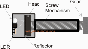
In the electromechanical arrangement shown in the figure above we are able to see the following integrated components:
A small gear attached with a screw mechanism.
The head of the screw having a white mat reflector surface
A LED/LDR assembly positioned in front of the screw head.
How the Proposed mechanism works.
The gear shown in the above figure is to be locked with another gear having a ratio that may be 10 times higher than this gear.
The bigger gear needs to be configured with the pedal mechanism such that it initiates a rotational movement in response to the pressing of the pedal.
The rotational response from the gears will in turn produce a forward motion of the screw head across the chamber where the LED/LDR assembly is located.
The process will cause a proportionately varying amount of reflected light from the LED to be received by the LDR.
This varying data (in the form of a varying resistance) corresponding to the pedal depression can be then fed to a signal processor circuit for enforcing the intended speed control of the particular vehicle.
In the next post we'll learn the signal processor stage using PWM technique.
In the above section I have explained about a simple electromechanical converter assembly for transforming the pedal action into a proportionately varying electrical signal.
Converting Pedal Action to PWM
Now let's study a circuit implementation which will enable us to convert the pedal electric signal into a correspondingly varying PWM signal for the intended motor speed control of the vehicle.
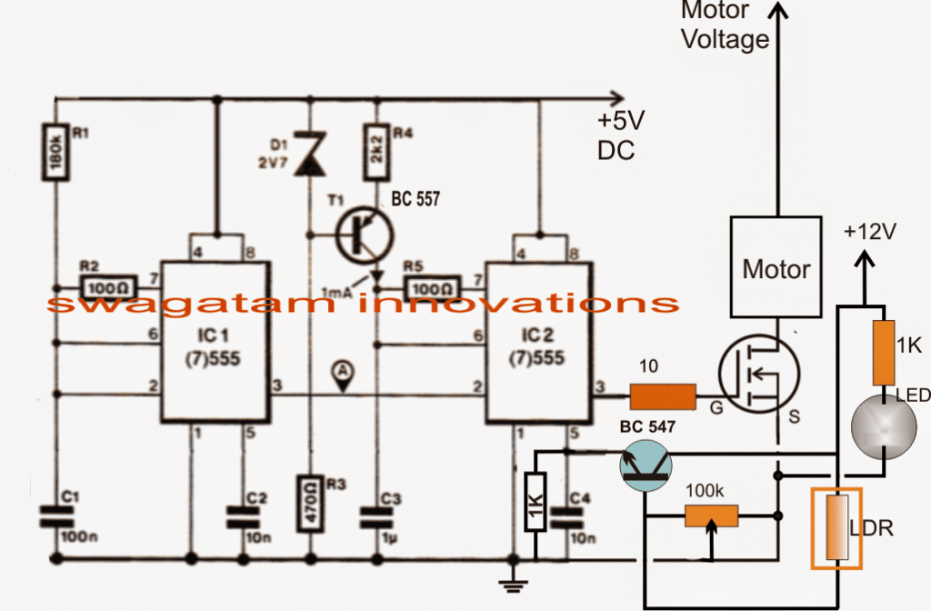
Referring to the above circuit diagram we can assess the circuit operation with the help of the following points:
IC1 is configured as a 80Hz pulse generator having maximum ON time and minimum OFF time as its duty cycle
IC2 is rigged as a comparator which first converts the above 80Hz pulse applied at its pin2 with triangle waves generated at its pin6 and compare the triangle waves with the modulating voltage available at its pin5.
The pin5 modulating voltage is derived from a BJT BC547 emitter which is configured as a common collector with its base connected with the LDR inputs achieved from the pedal actions.
The varying resistances in response to the pedal pressing is compared with the 100K preset setting and a proportionate magnitude of voltage is developed at the base of the transistor which converts the low current input into an equivalent high current signal over pin5 of IC2.
This instantaneous potential level is accepted and processed by IC2 generating proportionate magnitude of PWM signals for the mosfet and the connected motor.
The motor speed is thus controlled and varied as per the fluctuating PWMs in response to the pedal pressings of the vehicle.
The above procedures effectively convert the pedal actions into a controlled operations of the vehicle motor and its speed.
How to Set up the Circuit.
It's very easy.
- Press the pedal to its maximum point such that the screw head reaches to the nearest possible position in front of the LED/LDR assembly.
- Next adjust the 100k preset until pin3 of the IC2 starts generating PWMs with maximum width, this may be confirmed by measuring the voltage at pin3 to be as close as possible to the supply voltage of the circuit, that is 5V.
- Once this is done, the setting up procedure could be assumed to be complete.
- The results could be now verified by pressing the pedal at different levels and checking the motor speed vary in an identical manner.


Questions & Answers
Hi, I read the article and I noticed that Mr. Svyatoslav means to fit a hall sensor instead of a led and ldr to put on an ebike because ebike accelerators are with hall sensor because the potentiometer spoils the ideal 555 with a hall sensor and amplified by mosfet
sent – I hope for a positive feedback
Hello Svyatoslav,
yes I have seen the email, however it’s about bicycle pedaling, while the above article is about pedal accelerator for electric vehicles like a rickshaw or other 3 wheeler.
As far as I understand you need a pedal assistance for a bicycle which will upgrade the motor power as the rider tries to increase the speed of the bicycle by pedaling harder…
The concept is actually very simple. As the rider pedals harder, a Hall effect sensor converts the effort into wider PWMs on the motor and the motor gets proportionately more power and assists the rider in its effort to gain more speed.
Once the rider stops pedaling the reverse happens.
I may create a new article on this soon…
I apologize for the duplicates – the first time on your site.
Then I had a problem to make a logical Hall Sensor – linear … – the integrator did not help the situation.
Sorry, which circuit did you try. An integrator is not required since the output from a Hal sensor is not a a PWM?
I shake my hand, engineer!
The topic is very interesting for those who love not to lazily ride an electric bike, but also to help the motor by turning the pedals.
The mechanical assembly that you are proposing is difficult to implement – I think you can use a ready-made pedal assistant for magnets and 2 hall sensors for this purpose.
Please make a correction to the proposed scheme when using the Hall sensor.
Sincerely.
Thank you Svyatoslav
The idea proposed by me is actually very simple since it works with an ordinary LED and LDR, and its range is wider, may be from 30k to 500k.
A hall sensor range will be small within 2.5V and will require amplification and other settings.
The pin5 of the 555 IC2 works with a range of 3V to 10V, so amplifying the 2.5V range from the hall effect will require an linear voltage amplifier stage, which will complicate the system.
If you have a linear voltage amplifier circuit you can suggest, I’ll update the design accordingly.
If I am right. – in PAS with magnets (6-8-12 pulses per one pedal rotation as standard), logical Hall sensors (0/5 volts) are used.
The linear sensor is used in the throttle control knob.
I think that to increase the output voltage from the Hall sensor, you can use the simplest comparator.
I see the problem in that the torque on the wheel would be 80-90% of the applied effort on the pedals (to be adjustable, to help the legs).
An even more elegant solution, when using a standard controller on an electric bike, is to use the switch button “pedals – throttle” … (previously, nothing came of this idea)
Thanks for attention.
Thanks for your interest.
I am not sure how a comparator can be used to amplify voltage? A olatge follower might work, but it might not amplify the voltage.
Yes a finger operated switch would be a much elegant. A spring operated switch having a load cell at the base might do the job…
Good afternoon mr. Swagatam
Unfortunately, on this resource I can’t attach any file for explanation. (Better to see once than hear a hundred times)
I wrote a message and two pictures to your contact email August 21, 2019 8:12/9:11 PM. Please find in contact@162.240.8.81 and respond with your opinion.
I still have ideas for development in this direction, but they also require a graphic explanation.
Hello Svyatoslav, I checked my contact email, but could not find anything there, I even checked my spam folder, no emails there too. You can send to my gmail account.