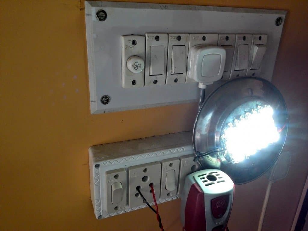
In this post I have explained the construction of a homemade 10 watt LED lamp using ready made 12 V SMPS adapter. The project was successfully built by Mr. Debabrata Mandal.
In many of previous posts I have discussed the use of 1 watt white LEDs for making high efficiency LED lamps for implementing in homes for high bright, low consumption illumination.
LED Tube without PCB
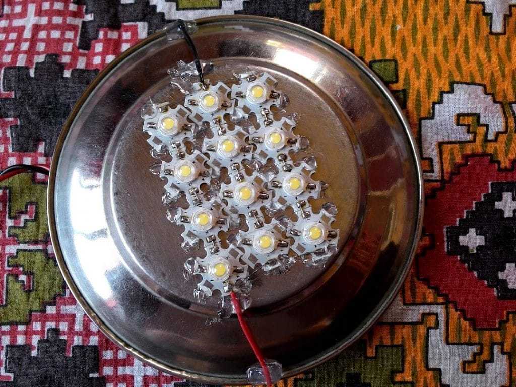
Here I have explained yet another interesting high watt LED lamp project which was constructed by Mr. Debabrata, using 12nos of high bright 1 watt LEDs fitted over a steel plate.
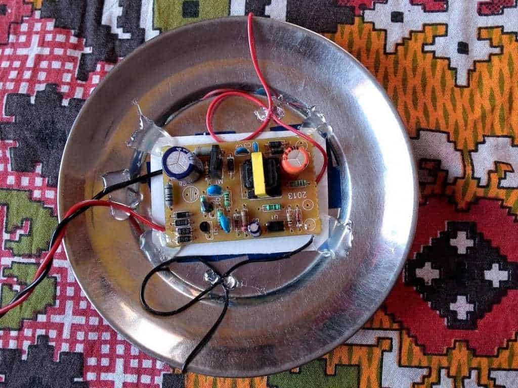
An ordinary $2 12V/1amp SMPS power supply was used for driving it. Remember I have already discussed the construction of this SMPS circuit in one my previous posts?
However in the proposed 10 watt LED circuit there are a few serious technical flaws which needs to be rectified for ensuring long life to the lamp and for obtaining optimal results from the unit.
The first issue could be with the use of steel material as the heasink. As we all know that steel is not an efficient conductor of heat, therefore it's definitely not recommended as a heatsink especially for LEDs which are highly sensitive and vulnerable to heat and current.
The rise in temperature within these LEDs could result in forcing the devices to suck more current which could eventually get transformed into a run away situation and permanent damage to the LEDs or weakening of their illumination.
Technical Specifications
The following response from Mr. Debabrata simply highlights the above issue.
Bro, these 1w LEDs produce GINORMOUS amount of heat.... daaaaamn with 12x1w... this steel plate aint dissipating enough. The plate area behind the led bunch is getting so hot tat those plastic glue is semi-melting & also heating up the smps board stuck behind
Can u tell me where i can get 1 foot aluminium strip? Kinda like a ‘scale/ruler’... so i can arrange the LEDs like a tube? ....wider light & more heat dissipation
Using Aluminum Heatsink Base instead of Steel
The above issue can be easily tackled by incorporating an aluminum plate instead of steel or iron. Size could be a matter of trial and error, it's always better to go for a much larger aluminum surface relative to the LED assembly dimension. Also make sure the plate is not thicker than 1mm, in fact the thinner the better, but not less than 0.5mm.
The above solution will definitely take care of the heat dissipation of the LEDs, however if the ambient temperature gets warmer, as we commonly experience in tropical countries during summer time, the above solution might not be enough and could start causing problems.
For this a simple yet effective solution is to incorporate a current limiter circuit in between the LED board and the SMP supply. This will restrict the LEds from drawing current beyond the set safe limit irrespective of the ambient temperature levelconditions.
I have already covered a very useful current limiter design in one y previous posts, so we can incorporate the same for the present design.
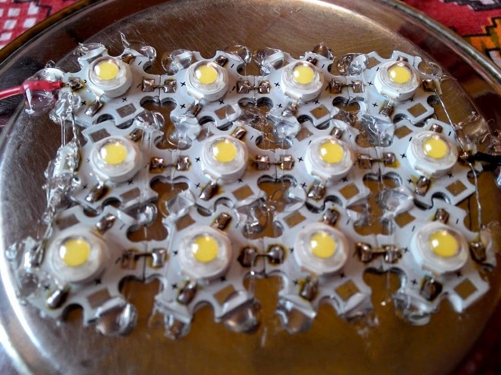
In the prototype images shown below we see that the LEDs are arranged in group of 4s, and the power supply used is 12V. As per the standard formula the arrangement will not require individual resistors, however since each LED would be getting only 12/4 = 3V,the illumination could get slightly lesser, because for optimal power a 3.3V is recommended for these LEDs.
You can again refer to the circuit and the formula presented in the above mentioned LED current controller circuit which shows a configuration using 3 LEDs in the series with individual limiting resistor.
The resistors perform the function of distributing the current equally to the individual strings so that the illumination is uniformly emitted across all the LEDs.
Here's a more comprehensive circuit which shows the correct method of employing high bright 1 watt LEDs for making 10 watt or higher wattage LED lamps for home decor and lighting:
https://www.homemade-circuits.com/making-led-halogen-lamp-for-motorbike/

Hello Sir. Can I used 12v 1amp smps adaptar for 10watt .
yes you can by using a suitable series resistor with the LED.
Hi Swagatam
Can you send me the ready to use assembled circuit for use with 15W LED Panel light? Pls let me know amount and how to pay it.
J Arvind
9820314545
Hi CM, sorry I don't manufacture or sell products…
please,Can you give me the source schematic bared!
[email protected]
wiring procedure is actually too simple, just make strings of LEDs (by connecting 4 LEDs in series), make 4nos of these strings and then join the extreme ends of these 4 strings with correct polarity, meaning all the anode ends of the 4 strings join together and all the cathode ends become common…..next connect these grouped ends to the 12V supply…strictly 12V…don't exceed this value.
hi swagatam sir i can u please design 32v 1.5amp led driver???
hi santosh, you can refer to this article:
https://www.homemade-circuits.com/2012/03/how-to-make-simple-12-v-1-amp-switch.html
you can simply alter R6 to get the desired voltage output
hi sir
i want to drive 40 1w leds the smps circuit is going really costly and complicated can i use transformer insted of smps what will happen with the power consumption? will it increase? decrease? or will be same?
Hi Vaibhav,
a transformer is the best thing that you can use. The power consumption will be as good as an smps provided you use a LM338 current limiter circuit with it as explained in one of my articles.
hi sir,
can you please guide me how to select high frequency transformer in smps for 36volt 1.5amp fix DC output.
Hi Vaibhav, it's a complicated process, will require a lot of calculations, it'd be better to consul a professional in the field.
I want to increase the power of my inverter
Pls how can I connect 2 9v 5amps CT transformer in parallel…… I saw it on this blog b4…. Thanks
what do you want to make?
hi sir
can you provide me any circuit for 20v 2amp smps
and wish u very happy new year in advance
Hi Vaibhav, i'll try to find a suitable design and inform you soon.
Wish you too a very happy new year.
please guru help me out on my circuit i ask for help. the one that close a relay for 8sec and delay it for one hour it should continue for 12hour before it stop.is for my project in school please help me design it thanks
Tim, please first complete the following circuit, this circuit can be used for acquiring the 8sec and 1 hour timing sequence….once you complete this successfully then i'll show you how to attach another stage with it for getting the 12 hour option
https://www.homemade-circuits.com/2012/04/how-to-make-simple-programmable-timer.html
hello brother.I am making 10*5=50 watts 12v i want to know that which value of capacitor and resistor i have to use…and can u please draw circuit as u did in other projects.
hello sheikh zeeshan, you can make the following design, use only 5 strings instead of 7 as shown in the design
1.bp.blogspot.com/-htEbdNoXVTY/UfdGhbVuQaI/AAAAAAAAE6A/NRDLuKUk9G8/s1600/motorcycle%20led%20halogen%20lamp%20circuit.png
sory sir i think u didnt follow my point, i am designing 50 watt led .
quantity:5 LED (per led 10 watt)
WATT:50
volts 12
now guide me that which value of capacitor and resistor i should use here. and any thing more which should use here
Still you can use the same circuit which was suggested in my previous comment, connect the 5 leds in parallel with individual resistors for each LED.
The resistor value formulas are given in the article itself.
….sorry this is the link you need to follow:
https://www.homemade-circuits.com/2013/06/universal-high-watt-led-current-limiter.html