Gunn diodes are semiconductor devices which are used to generate low-power microwave signals in a simple and low-cost manner. These have been in use for more than 60 years now. Gunn diodes can work with frequencies ranging from a few gigahertz to over 100 GHz. It was first discovered by J. B. Gunn of IBM in the early 1960s.
Today, Gunn diodes are being commercially used in a wide range of applications, including microwave data lines, low-powered FM and CW radar, intruder burglar alarms, etc. Under stable temperature and voltage parameters, circuits using these diodes can generate 15 mW to 1 watt of power and have low noise and excellent frequency stability. Gun diodes are especially well-liked by enthusiasts for use in amateur radios operating at 10 GHz.
Construction
A Gunn diode is manufactured from a single piece of N-type silicon. This is divided into three primary sections, as seen in Fig. 1.
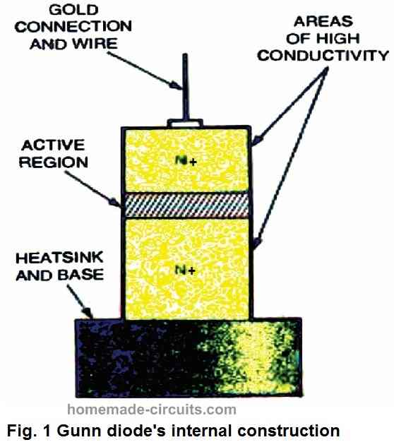
The device's top and bottom regions include N+ material which has been extensively doped, resulting in strong conductivity for interfacing with the external parameters.
A wire connection is attached to the conducting base on which the device is installed. The base of the device also serves as a heat sink to absorb the excess heat.
A gold link is placed on the top surface which connects with the diode's opposite terminal. To ensure exceptional conductivity and relative stability, gold becomes essential.
The device's active region is situated in the middle, which is less extensively doped and has lower conductivity. This is generally around 0.5 ohm per cubic centimeter, which indicates that almost all of the voltage applied across the device passes through this layer of the diode.
The average thickness of the diode's active layer is ten microns (0.001 cm). Its thickness would obviously differ from one diode to another because this primarily impacts the overall working of the diode. This implies that the operating frequency of this device is a critical element of its datasheet.
The Gunn diode has a unique design because it is made entirely made up of N-type material and does not have a P-N junction. In essence, it is not a conventional type of diode, rather functions on altogether different principles.
How a Gunn Diode Works
Although a Gunn diode's working can seem complex, it may be possible to understand it on a fundamental level.
The active center region of the device is subjected to the majority of the potential created by an applied voltage. This region is extremely thin, and even a little voltage shift shows a significant potential gradient or voltage fluctuation over a certain distance.
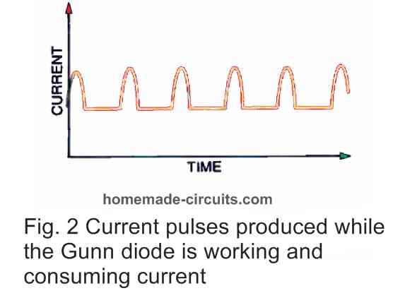
As illustrated in Fig. 2, a current pulse begins to flow through the active zone when the applied voltage across it reaches a specific level.
As a result, the rest of the active region's potential gradient decreases, which stops the generation of additional current pulses. Only after the current pulse crosses over to the opposite end of the active zone does the high potential gradient return, allowing for the generation of another current pulse.
If the voltage and current curve is plotted out, it is possible to see the peculiar current pulse activity from a different angle.
Difference between a Rectifier Diode and Gunn Diode
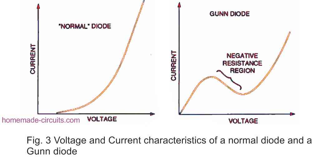
- The curves of a conventional rectifier diode and a Gunn diode are depicted in the diagram in Figure3 above.
- A conventional rectifier diode's current increases with voltage, however this relationship is not always linear.
- On the other hand, a Gunn diode's current begins to rise and, after reaching a specific voltage, begins to drop before increasing once again.
- Its oscillation properties are caused by this region where it drops, which is referred to as a "negative resistance" region.
Setting the Frequency
Although the active region's thickness determines the general operating frequency, it is still feasible to change the frequency across a specific range. Since the Gunn diode is a microwave device, it is typically installed in a wave-guide cavity to generate a tuned circuit. Its frequency of operation is determined by the resonant frequency of the entire assembly.
The tuning process can be accomplished in a variety of methods. By inserting an adjustable screw into the waveguide cavity, mechanical changes could be made, enabling a basic tuning indicator.
Nevertheless, electrical tuning is usually necessary as well, and one of two different methods could be used. The first method involves coupling a varactor diode into the Gunn oscillator circuit.
When the voltage on the varactor diode is changed, the capacitance changes, causing the frequency at which the entire circuit resonates to change.
Although this approach is inexpensive and simple to use, it has many drawbacks. Firstly, it has a limited operating range. Secondly, this technique produces a lot of phase noise, which might not be appropriate for many applications.
Using YIG for Effective Frequency Adjustment
Using a YIG material seems to be a more effective tuning technique. This incorporates Yttrium Iron Garnet, a ferromagnetic substance.
When the Gunn diode and YIG are inserted into the cavity, the cavity's effective size is decreased. A coil is positioned outside the waveguide to do this.
When a current flows through the coil, it has the effect of expanding the YIG's magnetic volume and contracting the cavity's electrical dimension. As a result, the frequency of operation rises. Phase noise is significantly reduced with YIG tuning, and a large frequency range could be achieved.
Using Gunnplexer For Amateur Radio
The Gunn diode oscillator is a component of a commercial transceiver offered by Advanced Receiver Research for amateur radio usage. The device, referred to as a "Gunnplexer," is used to produce and down-convert nominal amateur signals from 10 GHz to the amateur band on 2 meters (144 MHz), or other lower intermediate frequencies (IFs).
The Gunnplexer consists of a Gunn diode attached to a high gain rectangular horn antenna together with Schottky mixer diodes enclosed inside a 10 GHz cavity.
Frequency variations of up to 60 MHz from the normal resonance frequency can be achieved using varactor tuning. The Gunn diode operates as both a transmitter and a local oscillator for the down-converted 2-meter IF.

Comments
Please can you show example of gun diode in a circuit and it functions?