The small circuit that we propose here provides a 20 dB gain to the microphone signal, which will finally allow you to effectively use an electret microphone on your PC.
Circuit Description
The diagram of our circuit is reproduced in the Figure below.
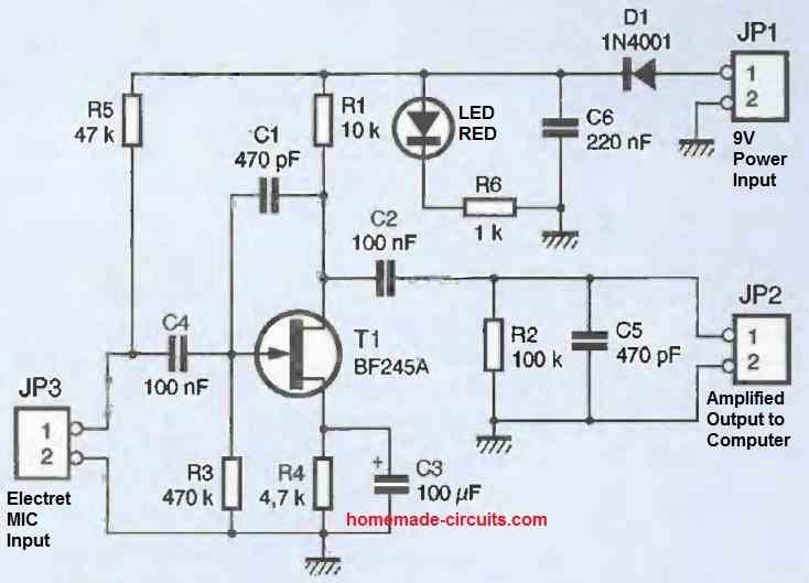
Don't expect a complicated diagram with op-amps everywhere, as our circuit is based on a simple BF245A field-effect transistor (T1 in the diagram).
The transistor is biased in a conventional way using resistors R3 and R4. The current flowing through the gate is almost zero, so the voltage developed across R3 is also zero.
T1 is a depletion-mode transistor, which means it conducts as long as the voltage between its gate and source is not sufficiently negative. The current flowing through R1 will develop a positive voltage that will raise the source of T1 to a higher potential than its gate.
T1 will therefore see a negative VGS voltage. This will limit the current flowing through R1, and the voltage developed across it will stabilize around the desired operating point thanks to the pinch effect of the transistor.
The signal from the microphone will be applied to the gate of T1 via the coupling capacitor C4 which will filter out the DC component due to resistor R5. This resistor serves to bias the electret microphone as your PC's sound card would do.
The signal from the microphone will modulate the gate voltage, which will also modulate the drain current, but in a ratio that depends on the value of resistor R1.
The amplified signal will appear across the terminals of R1 and will be transmitted to your PC's sound card (via JP2) through the coupling capacitor C2.
Capacitors C1 and C6 are used to stabilize the operation of the amplifier by limiting the high-frequency bandwidth.
As for capacitor C3, it serves to decouple resistor R1 to maximize the amplification of the circuit. Note that its value determines the low-frequency bandwidth, so don't decrease its value.
Power Supply
The circuit will be powered by a 9VDC battery connected to JP1. The D1 diode is used to protect the circuit in case of power supply connector inversion.
If no precautions are taken, this diode may add noise to the signal captured by the microphone.
Without the LED diode, the circuit consumption is very low (around 800pA). In this case, the D1 diode is biased in its knee (characteristic curve of a diode).
The amplified signal causing a variation in the current consumed by the circuit, the bias point of the D1 diode moves, causing a variation in the voltage drop across the diode, which is reflected in the supply voltage.
Moreover, the thermal drift of the transistor in T1 also produces minute variations in the current consumed by the circuit, which further increases the noise in the power supply voltage due to the D1 diode.
The problem is that, from a dynamic point of view, the power supply noise is entirely conveyed on JP2.
The few pV of white noise, attributed to the useful signal, will also be amplified by the sound card of your PC (gain of 40dB to 60dB).
If no special precautions are taken, this produces a perfectly audible hiss on recordings made from the microphone.
Why the Diode is Important
Of course, we could have removed the D1 diode to eliminate the source of the noise, but it is still useful to protect the circuit because it is common when connecting to accidentally present a battery with the wrong polarity (which would destroy transistor T1).
To eliminate the noise added by the D1 diode, we have shifted the bias point of the diode to a more sensitive area of its characteristic curve by artificially adding consumption to the circuit.
Role of LED
The LED diode DL1 will consume a small amount of current (around 8mA). Do not remove it thinking it will increase battery life. You would only degrade the performance of the circuit.
So, let's just say that an LED diode looks nice! Finally, capacitor C6 was added to further reduce the residual noise caused by D1 diode.
The results obtained are quite satisfactory, and you can judge for yourself.


Need Help? Please Leave a Comment! We value your input—Kindly keep it relevant to the above topic!