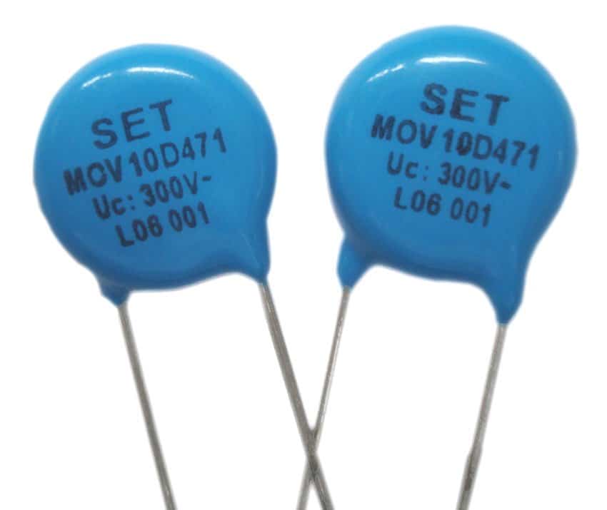
MOVs or metal oxide varistors are devices designed for controlling mains switch ON surges in electrical and electronic circuits. Selecting an MOV for a particular electronic circuit might require some consideration and calculation, I have explained the procedures here.
What are MOVs
Metal oxide varistors or simply varistors are non-linear surge suppressor devices which are used for suppressing sudden, high abnormal voltage transients or surges, especially during power switch ON or thunder lightening situations.
These are mostly used in sensitive electronic circuits for safeguarding against such catastrophic occurrences.
MOVs are basically non-polar, voltage dependent devices, meaning these devices will react to changes in voltage conditions.
Therefore MOVs are specified to trigger ON whenever the rated magnitude of voltage across their connections is exceeded.
This voltage rating at which an MOV may be rated to fire and short the transient to ground is called its clamping voltage specification.
For example, if suppose the clamping voltage rating of an MOV is 350V then it will switch ON whenever the voltage across it surpasses this limit.
When an MOV switches ON or is triggered by a high voltage surge it shorts the voltage spike across its terminals, preventing it from entering the vulnerable electronic device attached on the other side.
This action protects the electronic circuit from such accidental voltage surges and transient spikes.
And since the above reaction is sudden, MOVs are characterized as non-linear devices, which implies that these will not vary their characteristics gradually but suddenly when the specified parameters is exceeded.
The best characteristic of an MOV is its ability to absorb high current content accompanied with the voltage surge . Depending on the MOV specification the current absorbing capacity of an MOV could be anywhere between 1 amp to a massive 2500 amps
Current-voltage characteristic waveform of a typical zinc oxide MOV
However the duration of the current handling feature of an MOV may be limited to a few microseconds only, which means the activation of an MOV under such sever situations can not be more than a few microseconds, otherwise it could burn the device and damage it permanently.
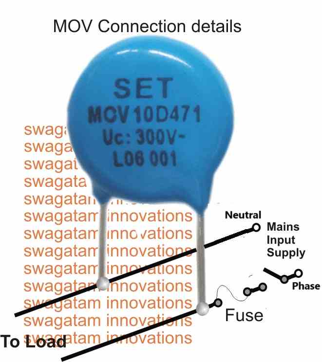
Therefore it is advised to use a fuse in series with the mains line in conjunction with the attached MOV for ensuring safety to both the electronic circuit and also to the MOV under a possible extreme catastrophic conditions.
ELECTRICAL CHARACTERISTICS
Typically the V/I characteristic of a ZnO varistor (MOV) can be understood with the following explanation:
The relationship between voltage and current of a varistor can be roughly estimated with the following formula
V = C x Iβ
where:
V = Voltage
C = Varistor voltage at 1 A
I = Actual working current
β = Tangent of angle curve deviating from the horizontal
Practical Example
When:
C = 230 V at 1 A
β = 0.035 (ZnO)
I = 10-3 A or 102 A
V = C x Iβ
so that for current of 10-3 A: V = 230 x (10-3)0.035 = 180 V and
for a current of 102 A: V = 230 x (102)0.035 = 270 V
Source: https://www.vishay.com/docs/29079/varintro.pdf
How to Select an MOV
Selecting an MOV for a desired application is actually easy.
First determine the maximum peak safe operating voltage of the electronic circuit which needs the protection and then apply an MOV specified to conduct near about this voltage limit.
For example, suppose it's an SMPS device with a max capability of 285V RMS from the mains input, implies that the unit would be able to handle a peak mains surge of not more than 285/0.707 = 403V
The 403V figure provides us the max peak mains handling capacity of the SMPS circuit which must be avoided under any circumstances and therefore an MOV rated with a clamping voltage of around 400V could be applied to this SMPS safely.
The current rating of the MOV could be twice that of the SMPS rating, meaning if the SMPS wattage is rated at 24 watts at the secondary, then the primary could be calculated as 24/285 = 0.084 amps, therefore the MOV current could be anywhere above 0.084 x 2 = 0.168 amps or 200mA.
However a 200mA MOV could be difficult to obtain therefore a standard 1 amp device could be used for serving the purpose with utmost efficiency.
Note: Many countries have adopted a harmonized standard for AC power grid voltage typically around 230V with a tolerance of +10% and -6%. This means, the acceptable voltage range can fluctuate between 207V and 253V. Previously, some regions might have had a nominal voltage of 240V with an upper limit of 264V. However, under the new standard, the upper limit would be 253V. Therefore varistors rated for 270V or 275V could be suitable for protecting against voltage spikes in these regions.

Questions & Answers
Dear Nordlike people,
why you are kum-like why change words od well known stuf. THIS WAS VDR= VOLTAGE DEPENDING RESISTOR. Who and why change it. With which purpose????
Metal Oxide Varistors (MOVs) are simply the most common modern type of VDR. No matter which name you prefer to use, they all serve the exact same purpose: protecting your circuits from voltage surges! Thanks for reading and sharing your thoughts.”
I see in my MOV’s datasheet that it has an operating DC Voltage of 38V and a clamping Voltage of 85V. Can you please explain the difference?
Thanks
– Andy
The 38V operating DC voltage is the maximum continuous voltage the MOV can handle while remaining mostly non-conductive, so under normal conditions it behaves like a high resistance and does not affect the circuit. Below this level the MOV is fully turned off…
The 85V clamping voltage is the level at which the MOV starts conducting heavily during a surge and limits the voltage by absorbing the excess energy.
In between these two levels, the MOV starts conducting slowly as voltage rises, until 85V is reached, when it conducts fully…
I have a VTS Diode that burned up and I am uncertian how to select a new one. It is a 120vac control panel with a on off switch that turna on a solenoid and a old maginetic size 3 starter from the late 60’s.
I think I need 120V clamp,bidirectional, minimum of 188 reverse. but not 100% sure.
In that case please do not use a TVS diode, use an MOV with a clamping voltage of 150V peak.
Hi – I need an MOV to repair a bass guitar amplifier: TC Electronics RH750 model.
The MOV has become partly blackened which makes reading the value difficult but it’s in-circuit with 3 X 220R resistors in parallel which monitor the high dc voltage.
Would you happen to have any information on this amp please..?
Thanks, Paul
Hi, can you please tell, where was this MOV connected in your amplifier unit? I will try to figure it out…
The 5vdc is an output from a PLC that goes to a normally open limit switch and when closed returns to the PLC . The 24vdc is just a start signal to energize a relay. I want to protect the PLC from any induced or stray voltage coming back on these paths.
In DC circuits, reverse voltage can be blocked or bypassed using diodes. If you are concerned about high frequency noise then that can be eliminated by connecting capacitors across the supply line. I don’t think an MOV would be required in your case.
I have a 5vdc device and a 24vdc device to protect. What size MOV would I need? Thank you for taking my question.
most mov not had that’s lowered voltage tester ?
Please provide more details regarding those devices, so that I can understand where the MOV needs to be installed?
Hello! Can I use a tester to check the MOV VDR surge protectors or does the signal go through? I tried, but no signal goes through.
Hi, if you want to test an MOV, you can try the LAST circuit design explained in the following article:
https://www.homemade-circuits.com/testing-mov-metal-oxide-varistor-surge/
Which value mov can use for 230v RMS incoming Of full load current 6 Amp.
for 230V the MOV rating can be 310V….current has nothing to do with MOV.
Does mov works best in DC voltage system ?
Yes, it will work with DC circuits also…
electric door strike call for MOV but not sized Need Help The strike is set up as 12-24 vac intermittent .280 – .565 A 37 0hm
You can use a 14V MOV for the 12V system and a 28 V MOV for the 24V system.
This is also my question, as I install electric strike and maglocks. Can I jump on the back of this question and ask if when you say use a 14v and a 28v MOV is that referring to the clamp voltage? I have been looking on the RS and farnell website but cannot find them. Would you have a part number?
Yes, I am referring to the clamping voltage, you can find part number in these datasheet:
https://4donline.ihs.com/images/VipMasterIC/IC/LFSI/LFSI-S-A0007103731/LFSI-S-A0007103731-1.pdf?hkey=6D3A4C79FDBF58556ACFDE234799DDF0
https://in.element14.com/c/circuit-protection/tvs-transient-voltage-suppressors/tvs-varistors?voltage-rating-vdc=28v
Thanks for the reply but I am obviously missing something. Looking at the link you sent for the 28v MOV in the description it says the clamping voltage is 77v and not 28
https://in.element14.com/c/circuit-protection/tvs-transient-voltage-suppressors/tvs-varistors?voltage-rating-vdc=28v
And the littlefuse datasheet I can’t see one that will be correct for a 12dc lock. I have tried to read up on this and asked lots of questions but never really got a definite answer 🙂
Yes, the problem is that the MOV Clamping voltages are tied with their fixed Continuous voltage specifications, so even if we get the desired clamping voltage rating if it doesn’t match the continuous voltage rating, then it won’t be applicable.
I think instead of an MOV it is better to have a BJT voltage regulator, which can be customized as required.
merci pour toutes ces infos , moi je met GMOV juste derrière le disjoncteur , et ça fonctionne !!!!
Thank you Laupin, Glad it worked!
Hi I have a control panel with 24 vdc relays inside that turn on and off what MOV do i need to protect from on/off surges. Thanks
Hi, what exactly do you want to protect, is it the relay or the load connected with the relay contacts? And what voltage is used with the load and the relay contacts?
Ho can I protect with an mov a fridge compressor with 15 LRA and 1/3 hp? Standard 120v house currently?
The circuit in your diagram is dangerous.
The switch AND fuse should be in the live side. Assuming switch is in Live side, a blown fuse would leave the circuit at mains voltage.
Thank you for notifying the issue, I have corrected the diagram accordingly.
Yes, to some extent, against extremely short voltage spikes.
Hi sir, I’m curious about purchasing. When I am trying to buy mov there is too many different Voltage filters which I am drowning among them. For example in your example we found we need the MOV’s AC and DC voltage values. But there is Varistor Voltage, Clamping Voltage. I these values need to close to operating voltage. For example I found Mauser 331KM(E,N)20 for your circuit. It’s Vac 210v Vdc 330v. But It’s Varistor Voltage is 330V Clamping voltage is 550V. So is this Clamping Voltage is the maximum voltage it can handle or the value which lowered to after peak. Also in max continuous oe allowable voltage is lower than nominal voltage so I am really confused. Isn’t the nominal or rated voltage equal to systems operating voltage? I hope I have made myself clear and understandable. Love this site and your great work btw.
Sincerely
Hi Bahadir,
The crucial aspect while selecting an MOV is its clamping voltage which must be slightly higher than the peak input voltage of the application. For example, the 220V AC is the RMS voltage and its peak voltage will be around 310V, so the MOV clamping voltage could be around 330V.
can MOV be placed in power extension board to save Airconditioner by voltage higher than 260 V ac
MOVs can stop high voltages which occur only for milliseconds, anything higher than that can burn the MOV itself.
I built a power strip/extension for my hifi/pc systems and I want to add a MOV in each power socket. There are 4 of them in a star configuration.
The voltage is 220v where I live and the the current reaching the power strip is 16A.
What varistor should i use for this application? voltage, amperes and diameter.
You can use standard MOVs having a clamping voltage rating of 350V
I have luminous shakti charge 1450 inverter
Please tell me which MOV to be used in input line or ele.supply line.
If your inverter output voltage is 220V, you can use a 350V MOV.
How can I build a DC battery charger from AC source without using transformer
You can use an SMPS power supply.