This sound activated remote control circuit can be used to operate any electrical load ON/OFF, through a double sound command. Thus, the circuit ensures that the load cannot be operated through any random single sound triggers, which makes the circuit very fool proof.
Our device will require two shifted sound commands. However, the second sound command must be generated precisely at the moment when a green LED prompts the user to confirm the first received sound. This way, we eliminate accidental or random activations.
How the Circuit Works
The sound sensor will, of course, be a small microphone, specifically a tiny ELECTRET-type capsule that already has an internal first amplification. We invite the reader to follow these explanations in the diagram proposed in Figure 1.
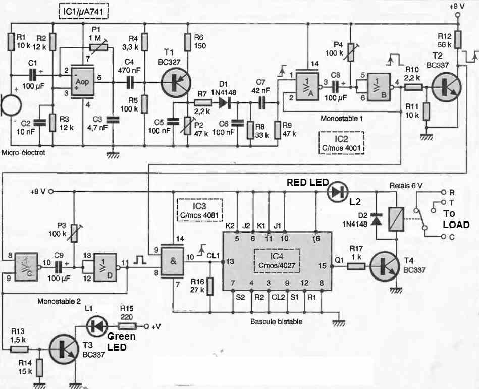
The sensor is biased in the correct direction through resistor R1. In the presence of any sound or noise, the microphone capsule generates a very low variable voltage that will be applied across the electrolytic capacitor C1 towards the inverting input of the operational amplifier IC1, a common circuit with a 741 op-amp in a DIL8 package.
The other non-inverting input is biased to half the power supply voltage through the voltage divider formed by equal-value resistors R2 and R3. The significant gain of this stage is also adjustable using the potentiometer P1.
Next, there is a transistor stage built around T1, which will be adjusted by the P2 setting so that in the absence of noise, the potential of the collector is zero.
The diode D1, along with components C6 and R8, forms an integrating stage responsible for converting the multiple sound pulses captured into a single positive pulse with rising edge.
This unique positive front received at each given order in front of the microphone is applied to the input of a first monostable flip-flop built around NOR gates A & B.
The duration of the created positive pulse depends on both capacitor C8 and the adjustment of adjustable P4. This period is approximately 2 seconds.
With the help of transistor T2, we invert this positive signal to obtain a precisely delayed positive front of 2 seconds. This new rising edge is used to perform two separate commands:
- First, triggering another monostable flip-flop built around NOR gates C and D of the same C/MOS 4001 circuit identified as IC2. A positive signal of approximately 1 second will be sufficient for further processing.
- Secondly, it is intended to indicate to the user that the initial sound has been successfully captured, and to do so, we light up the green LED L1 through transistor T3. Construct a bistable flip-flop.
We have seen earlier that after 2 seconds, we have a high logic state taken from the collector of transistor T2 and applied to the AND gate IC3 (pin 9).
If another high level reaches this logic gate, its output pin 10 will be high and will control the clock input CL1 of the IC circuit, ultimately a classic JK flip-flop implemented using the C/MOS 4027 circuit.
These two conditions will be met if the user gives a second command in front of the microphone while the green LED is illuminated. This way, we eliminate almost all unintended triggers.
By connecting the J and K inputs of this so-called "master/slave" flip-flop together, we easily create a bistable circuit, similar to the well-known circuit used in lighting systems.
It is important to connect the unused Set and Reset inputs to the low level, as well as the other CL2 input. The next steps can be easily deduced: for each new positive pulse at the CL1 input, the output Q1 (pin 15) changes its logic state.
It controls the base of transistor T4, which, in turn, powers the coil of the small relay.
The coil also serves as a current-limiting resistance for the series-connected red LED. Diode D2, connected across the coil, absorbs the back EMF when the coil is switched off, thereby protecting transistor T4.
The available contacts of the chosen relay can be used effectively.
Construction
The copper board containing all the components is shown at a 1:1 scale in Figure 2.
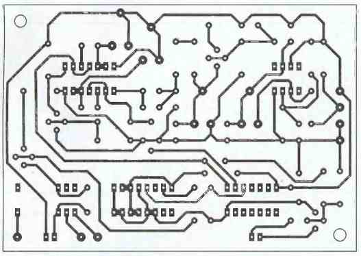
Before etching it, make sure that the chosen relay matches perfectly, with two normally open contacts.
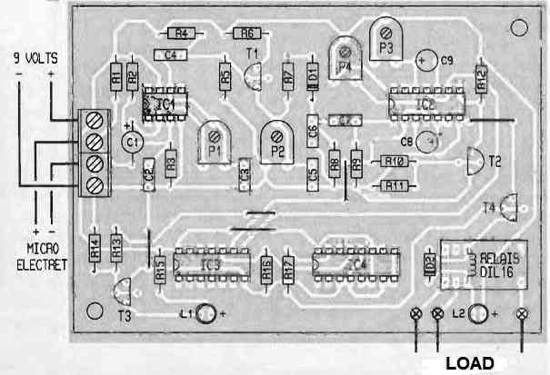
Despite that, a few jumper wires will still be necessary. Also, ensure that the various polarized components (diodes, transistors, electrolytic capacitors) are correctly placed.
If possible, mount the integrated circuits on a reliable socket to avoid excessive heat on the soldered components and facilitate potential maintenance operations. Finally, provide a continuous power supply between 9 and 12V.
How to Test
The adjustment is straightforward: P1 and P2 can be left at the midpoint. P4 should be adjusted to a duration of 1 to 2 seconds, which can be evaluated using an LED indicator on the output of the monostable flip-flop 1.
The adjustment of P3 is simply related to the lighting of the green LED L1 by setting pin 8 of IC2 to a high level.
This control stage can be used to power up your laboratory power supply when both hands are not available.
Another use is to place this module near a television equipped with a remote control that has a power on/off button. This way, you can remotely turn on or off the device by toggling the sound. It's worth experimenting with.


Need Help? Please Leave a Comment! We value your input—Kindly keep it relevant to the above topic!