In this post I have explained how to transmit Internet data through LiFi using a class D amplifier as the transmitter and an ordinary audio amplifier circuit as the receiver.
How Li-Fi Concept Works
If you are wondering how a LiFi concept could be used for transmitting USB data, this article will provide with all the details you required.
We know that a Li-Fi concept is used for transmitting a digital data across a given premise more efficiently than any other means invented so far, especially because the Li-Fi idea allows the user to transmit the data and additionally illuminate the area where it's been installed, so it's like getting two crucial benefits from a single unit.
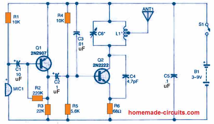
Remember our age old film projector device? It's probably the oldest known method of using light for transmitting data (picture).
Although we always had other great means of transmitting wireless data such as Wi-Fi technology, RF circuits, etc, using light for this purpose was never imagined simply because lights have been always considered as low-tech units, and thus underestimated, until the day when Mr. Harald Hass discovered this hidden potential of lights (LEDs), and showed the world how LEDs could be actually used for transmitting data in a much efficient way than any other contemporary techniques.
In one of our earlier articles I have explained through an example circuit regarding how to effectively transmit audio signal through a Li-Fi, in this article we'll go a little further and learn how to transmit an USB signal through Li-Fi.
Since LEDs are semiconductors devices these become perfectly compatible for handling digital data without any form of distortions. An LED will replicate and transmit the input content exactly as it was in the original source, and this property make LEDs extremely easy to configure for the intended purpose.
So far we have understood that Li-Fi is a method in which LED is used for transmitting a high frequency content within an enclosed room, which effectively transforms the LED into a wireless transmitter as well as a light producing device.For example Li-Fi concept can be used for transmitting and receiving a music data by using an LED as the light source and also a wireless music transmitter.
However the biggest challenge is to use a Li-Fi circuit for transmitting Internet data using ordinary parts and without involving complex and difficult to get components or MCUs.
A USB connector basically consists of the following wiring details:
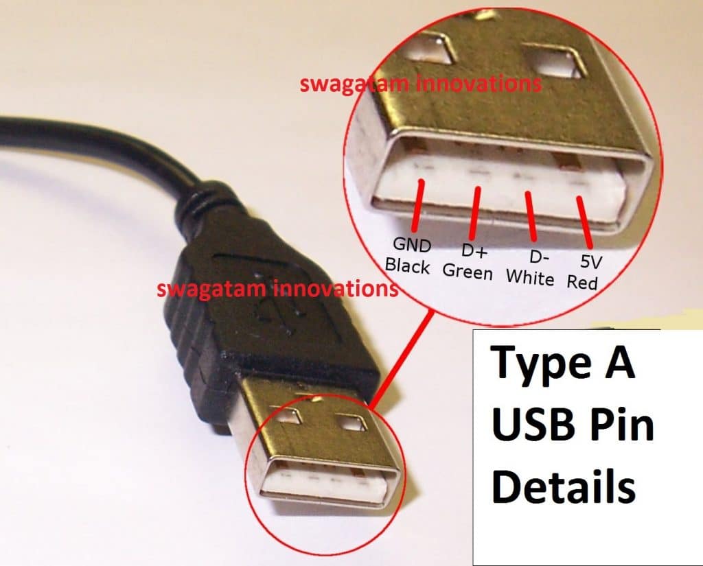
1) +5V
2) Ground
3) +D
4) -D
The +5V and ground are the supply out terminals which are normally used for powering the connected external device.
The +D, and -D are the data communication terminals which produces the complex differential signal across each other in a push-pull manner, meaning the +D is referenced to -D, while the -D signal is referenced to the +D terminals. This is what makes transmitting Internet through LED so confusing and complex.
This forced me to think of an alternative and more efficient design, that could actually transmit an USB internet data through LED Li-Fi circuit, without distorting the actual signal, and by employing ordinary components.
After some thinking I came up with the following circuits which hopefully would enable transmitting internet through LED light.
For the transmitter I decided to use a simple differential amplifier circuit module using IC BD5460, the following image shows the basic layout of this amplifier circuit.
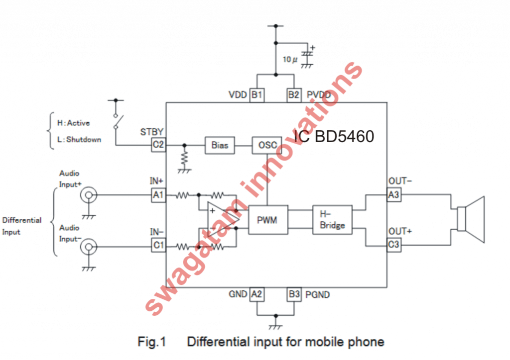
I modified the design into the required Li-Fi transmitter circuit for making it compatible to internet signals, as shown below:
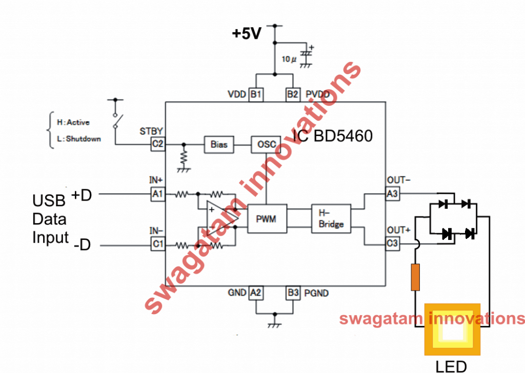
We can see how the differential music input terminals are used for receiving the internet data, while the output is connected to an LED via a bridge rectifier.
Using a bridge rectifier appears to be a smart idea, otherwise it would be simply impossible to transmit the push-pull signals through a LED, since an LED would simply fail to differentiate between these two signals.
By using the bridge we have effectively enabled the LED to recognize both the halves of the USB signal and send it to the receiver without causing any distortions in the original content.
The Receiver Li-Fi Circuit
Now the next challenge for me was to ensure that the rectified pulsating internet data through the LED is correctly decoded back to the original differential form in the receiver section.
This looked difficult however the simulation could be quite easily accomplished by using a dual supply based power amplifier circuit, for example the 100 watt mosfet amplifier already published in this website efficiently fulfilled the intended purpose as shown below:
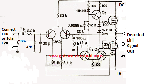
The BJTs and the mosfets can be any general propose rated to work with 12V/1amp supply. However if you want a powerful decoded output you could very well keep the original values for the devices and enjoy a powerful LiFi decoded inernet output.
UPDATE:
In the discussed concept we used a class D amplifier for the LiFi transmitter, however a class D amplifier essentially involves PWM for processing the input, which could be highly undesirable for an internet data to go through.
We do not want to distort or modify the complex Internet data in any manner, therefore a class D amplifier perhaps cannot be applied for an internet LiFi.
As per my assumption we don't need a classD amplifier rather only a BTL amplifier, which does not involve a PWM function, an example design can be witnessed below using the IC TDA7052.
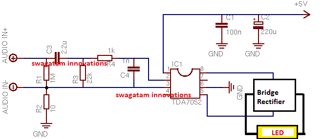
Now this looks perfect, and seems like the Internet data would be transferred to the LED without going through any sort of artificial transformation.
To start with we can go with this 1 watt amplifier circuit as the Li-Fi transmitter and use a 1 watt LED at the output. The idea will confirm whether the proposed Li-Fi transmitter really works or not.
If you have any further doubts regarding this simple yet seemingly working LiFi Internet transmitter circuit you can feel free to express them in the below given comment box.
Adding a Push Pull Stage
In the above diagram everything looks great and it seems the circuit is ready for transmitting the Li-F- data without any issues, however there seems to be a little flaw in the design.
What happens if there's no data at the input? The LED would simply shut down, and that's something totally unacceptable in a Li-Fi concept. Therefore we must somehow make sure that the LED always remains illuminated regardless of the input variations or presence of an input data.
In order to satisfy this condition, we need to introduce a basic LI-FI BJT push pull stage, which was already discussed in our first Li-Fi article.
The following image shows how to do it:
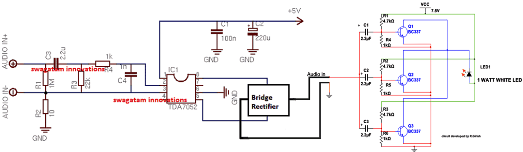
The above design now looks to be a perfect Li-Fi internet transmitter circuit without any flaws.


Questions & Answers
can We use TDA7052A ic rather than TDA7052 in transmitter cirrcuit
According to me both are one and the same so can be used
sir is this system bi-directional.
No it is not bidierctional
How can we connect reciever to mobile or laptop, to check whether internet is working?
how is it called an Li-Fi ‘internet transmitter’ if the input connection is in the form of audio signals??????? how you would connect that to an internet connection?
Internet or wifi signal waveform are also made up of radio frequency RF, so possibly these waveforms can also be transmitted using the above concepts, through LED.
Can this thing transmit internet connection?
Can you please say that how to transmitt(Text, imiage and video files) and Arduino code for that using Li-Fi or VLC…
That can be too complex, beyond the scope of this design
Ya you correct,It will be a bit more complex to handle….But it couldn’t be an impossible task…So will you please give me an idea about that a little bit☺
Please build the above simple design (with proof), if you succeed, then we can move ahead with more complex ones!
sir at the reciever end we get a single data line as the decoded output , but how to access that data , or how to connect that pin to a computer to recieve that data back ?
Nagesh, please tell me what exactly do you want to transfer, then I may try to suggest!
I want to transfer some sort of data , might be some USB data or internet data or any files from one computer to other or to other USB device .
In that case, the receiver will connect with the USB device, and the transmitter with the computer source, as explained in the above diagram. The data exchange will take place through the LED light from the transmitter.
Sir
Is ‘LM358 Gain Amplification Operational Amplifier Module’ is ok as transmitter???
Thank you for your help
Hi Sorry to disturb you again but the computer is unable to detect the transmitter and receiver both
is there any software to do that if yes can you plz mention it
is any external power supply is required
Sorry, I do not know about any software that can accomplish this
Avadhoot, According to me it should be a differential amplifier as explained in the article, you can also use the IC explained in the following article…
https://www.homemade-circuits.com/lm4862-amplifier-circuit-better-lm386-alternative/
Sir
Can u make a tutorial video and upload it to the website
It would be of so much help
Avadhoot, due to lack of time this won’t be possible at this moment, in future I may try to update it…
This is hardly a new idea, a friend of mine did a schools project transmitting audio by light in 1977 worked ok he initially used AM which i think you are doing here but switched to FM as quality was very poor, he used old torch light bulb so FM was easy as he modulated the freq of the ac supply voltage. I suspect you are AM only as an LED is basically a semi conductor Laser therefore frequency cannot be changed. Id be interested in the expected baud rate. May be some sort of swpwm on the voltage would work, if so try it using an analog modulated Laser diode would get good range and if the data rate is high enough a great product.
hello is it possible to transfer internet in lifi? and possible then how is it done what is procedure ,circuit diagram how convert internet signal to light signal and how to receive light and how to convert into internet signal in receiving side?
Sir which cable to use as output and how to connect it with circuit.
It’s through the USB cable, see the diagram on the top for the USB cable pin details.
Sir
This LiFi internet is giving me mad headache
I want to ask the internet transmitted into the LED bulbs where is it gotten from
I think from an ISP using cables if such lEDs exist?
Hello sir. I am looking for the detail circuit explanation of the Li-Fi transceiver, please sir if you could please share me ur circuit design and configuration mode on desktop. since am trying to transfer data between two computers using lifi.
Hi Zagol,
I have not yet practically verified this concept, however according to me the following block diagram should work
But it will need to be verified by somebody truly knowledgeable in this field.
sir
kindly help me with detailed steps on how to create an optotransciever on an empty copper substrate board
need detailed step by step help in making a lifi ethernet transceiver at home from scratch on an empty circuit board and how to configure it to browse the internet on desktop operating system I have the empty circuit board, op amps resistors and capacitors Help!!!!!!
sir
thanks on your response once again.
you know the photo detector is of two types the PHOTOVOLTAIC which is anticlockwise and the other
I think the PHOTOVOLTAIC is preferably used
Do u think the usb plug’s amplifier will be photovoltaic when i plug the male to male usb chord from the female part of the 3.5 watts solar panel to the female port of the usb plug after removing the circuit board of the usb plug and removing the wire that links the plug to direct current?
sir are u saying if I beam my 18 watts streams of LED panel lights on the solar panel (photodetector) connected to the usb plug circuit that the usb plug circuit will amplify the voltage as seen from the solar panel to a voltage that will allow for internet transmission and received by the system for browsing free?
Bearing in mind that this panel is connected to usb hub with 4 usb female ports inwhich i have pluged the solar panel extended male usb chord in one of the 4 usb hub’s female ports with the USB charger plug’s circuit as amplifier also connected to one of the 4 USB hub’s port close to the port where i connected the solar panels usb extended chord
Sir what will the configuration on the destop system be like for me to start streaming live internet videos
is the amplifier responsible for the high bandwith or speed of the internet connection?
how does the speed of the internet in bytes/s relate to this amplification?
kindly respond in brief details as you travel through my words and lines so i can properly grab the worlflow ,logic and principle behind this because am scared my wild imaginations might not work
THIS SOUNDS LIKE MAGIC TO MEEEEE
HEHEHEEEE!
HELP?!?!?!!!!!!!!!!!!!;!;!!;;;!!!!!!!!
Hi ololu,
As I said earlier I have only tried to present a concept regarding how digital signals could be processed using a bridged amplifier circuit. The concept will need to be verified step wise by first making the above explained 2 input amplifier and then subsequently using more inputs for implementing an internet LiFi transfer.
I do not have any advanced knowledge regarding this field at this moment
sir
I am new to circuit board creation
in trying to create a transimpedance amplifier for a lifi internet receiver,what kind of operational amplifier (op amp) or integrated circuit (IC) is best for this amplifier.
Sir,does the arduino circuit board of a USB phone plug that goes to direct current have op amps in them?
The transimpedance amplifier must have 2 female port first for an input 3.5watts solar panel which will act as a photodetector while the second female port will act as the output that leads to the desktop system
sir,what is responsible for the creation of the internet bitrate as the amplified voltage enters the desktop system
sir, is it possible to use 2 operational amplifier to have an optimal voltage output from the transimpedance
Sir,can the op amp be refered to as a COMPARATOR?
sir,what is the relationship between components in the transimpedance amplifier with the byte/seconds or kb/seconds or GB/seconds
sir,do i need to integrate a java program into the transfer impedance amplifier for it to run in the desktop or is all that taken care of by java in desktop already
sir,how is the internet from the lifi after receiving it into the desktop configured to work in the windows operating system
if i have to integrate java or any program how do i go about it
please be explicit in your detailed explanations in response to my quest
HELP!!!!!!!!!!!!!
sir
i am aware of the solar LiFi internet and i want to know if my 3 watts solar panel with the USB integrated can also be used as a photo detector to receive and transmit binary data for internet browsing kindly help out on this
Ololo, if the LED light is able to collect optimally on the solar panel, then it can be used
Sir
Thanks on the receipt of your mail
From my last responce did i sound like i missunderstood u kindly meticulously go over my last mails and correct my flaws
You dwelt lagely on the transmitter circuit i saw that and told u i already have three LiFi panel lamps of 6watts each for a transmitter section and lamps beams magnificently i hope that is OK for internet transmission
I went on to talk about the receiver section where i will be using a solar panel of 3watts instead of silicon photodiodes or whatever to be used.
My fear is the amplifier that should amplify and process currents from the solar panel into binary data to be received by desktop.
So i thought of the usb plug circuit where u plug in the usb male mouth before pluging to light to charge ur phone.
I opened it and saw it had a space for photodiode which was absent
Then i also observed it had a female USB port where i can connect a male to male USB chord from 3 watts solar panel female USB port to it
There is an amplifier circuit on the PCB of that USB plug correct me if i am wrong
I think using that amplifier circuit with my solar panel embedded to it and then linking them with a USB hub to the desktop might give me an internet lifi dongle receiver for my desktop
Help!!!!!!!!!!?
Ololo, Your approach seems to be OK and it makes sense, and the USB plug should be able to process things correctly as per the computer internal specifications.
According to my understanding you should go ahead with this and let us know about the results.
I would appreciate if you could share your schematic with us…
Sir
Let’s take it from the transmitter section
I have made three LED panel lamps of 6 wattsw each with LED as a semiconductor ,when i plug this directly to light of the mains in my home and it beams isn’t that some internet data streams from a VLC waiting to be converted at the receiver section?
From the transmitter section let’s see the receiver section
Streams of Beam from my three 6 watts LED PANEL lamps emitted to fall on my 3watts solar panel with female USB port integrated into for output as my photodetector because emerging energy from the LED PANEL lamps has to be more than the energy on the cells of the solar panel in order to excite the molecules of the solar panel
I now see the need for an amplifier circuit with usb female ports for input and output where i will be connecting the male to male usb chord from female output port of photodetector to female input port of amplifier
The usb chord or usb to RJ 45 chord from the female output port of the amplifier is connected to the system giving the system binary bitrate internet
The amplifier for my 3 watts photodetector is my problem now
Kindly help a design for lifi internet receiver that best fit
Or kindly suggest device with such amplifier i can use
I intend creating such simulated amplifier with female usb input and output on the bread board and then on the printed circuit board
Will this work
HELP!!!!!!!!!!!!!!!!!!!!!!
In the above article I have only tried to explain a digital LiFi concept with two input signal, such as from a USB.
It is recommended that you first understand all the details carefully, then make a sample design exactly as explained above.
If you are successful, then you can try upgrading the above idea by adding more such units together to handle multiple inputs from a internet source.
sir ,how can i get a USB cable connected to server, i mean connected to internet source.
milind, I am sorry the title is mistakenly mentioned as internet transmitter for the above article. The circuit is actually designed for handling USB data and not internet data.
Hello but u told me this set up covers LiFi internet transmitter and receiver why saying its just usb data in response to milinds ?
Would this circuit transfer files from Mobile to PC? Apart from this circuit what to do in the mobile to send file? from File Manager then? How & what to select Destination?
Oops. ok. I missed that.
How do we do Bidirectional data transfer using single USB port?
As per my assumption, when the USB module LED light hits the sensor of the mobile module, the two counterparts should start communicating just as they would do with a direct connection.
to have a bidirectional exchange the mobile side should also have its own Tx LED module separately installed, and the USB side with a Rx…
The above basic set up explained above is for experimental purpose onlyt and recommended for basic applications such as listening to music from USB etc.
Hi,
I meant Internet browsing where we send request to the server and then we get the information. How can it be done ?
In the above article only the USB port’s communication has been discussed not the modem side, modem side could be a little more complex.