Semiconductor LEDs (Light Emitting Diodes) produce light when current flows through them. In comparison to conventional lighting sources, LEDs offer a number of benefits, including high energy efficiency, extended longevity, and low thermal output.
The forward voltage drop of an LED is one of the important factors that affects how well leds performs. We will go through how to measure the forward voltage drop of LEDs in this post.
Basic Working
A 3.7V cell is used whose voltage is boosted to 25V using a voltage booster circuit. This boosted voltage is applied to an LED through a 2.2 K resistor.
This resistor allows a low current voltage to be presented across the LED so that the voltage can drop and adjust exactly to the forward voltage drop of the LED.
The boosted 25V allows the testing of many series connected LED s which may have a total forward voltage drop of upto 25V. A digital voltmeter is finally used to measure the voltage drop across the LED which is equal to the forward voltage rating of the LED.
Forward Voltage Drop of LEDs
The voltage needed to switch on and produce light from an LED is known as its forward voltage drop.
The particular type of LED and the element utilized during its manufacturing affect the forward voltage drop. The forward voltage drop of LEDs typically falls between 1.5V and 4V.
While constructing LED circuits, the forward voltage drop is a crucial factor to take into account because it defines the power supply voltage needed for the circuit.
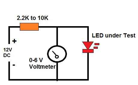
Block Diagram
The following figure shows the basic block diagram of the LED forward voltage drop tester circuit. It simply shows how the tester could be built using a 12 V DC supply, a 6 V voltmeter and a limiting resistor.
Method to Find Out Forward Voltage Drop of LEDs
To find out the forward voltage drop of LEDs, we can use a simple circuit consisting of a voltage booster, a resistor, and a digital voltmeter. The complete circuit diagram is depicted below. The 3 V booster 25 V boost converter can be purchased readymade from any online spare part store.
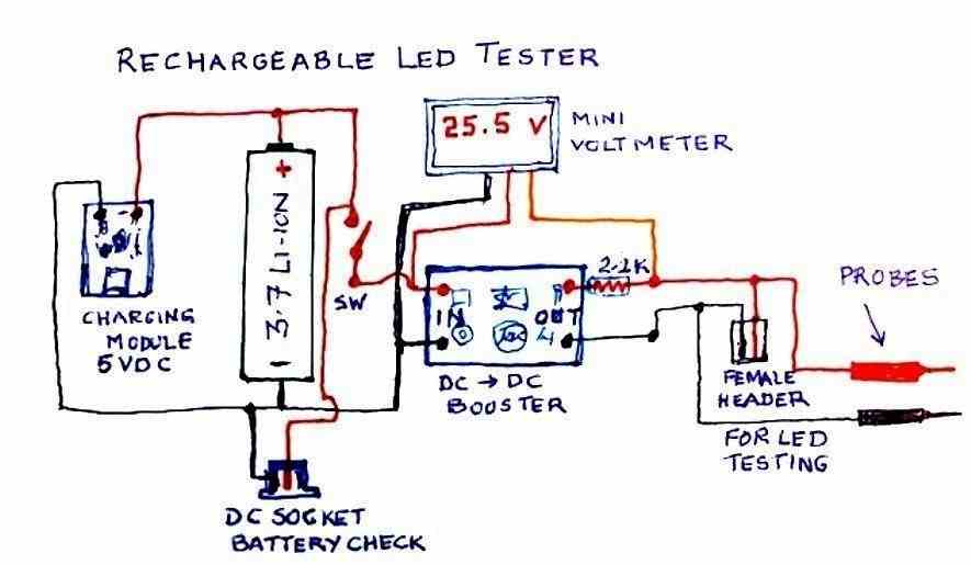
The voltage booster is used to boost the voltage of a 3.7 V cell to 25 V, which is sufficient to test many series-connected LEDs that may have a total forward voltage drop of up to 25 V.
For testing single LEDs, there is no need of using the boost converter, you can simply test it through a 5 V DC supply with a 2.2 K resistor in series.
The resistor is used to limit the current flowing through the LED so that the voltage drop across the LED can adjust to its forward voltage drop.
Any resistor between 2.2 K and 10 K is suitable for this purpose as it allows a low current voltage to be presented across the LED. This restricted current helps to prevent the LED from burning out due to excessive current.
The digital voltmeter is used to measure the voltage drop across the LED, which is equal to its forward voltage rating.
The voltage drop across the LED is measured by connecting the positive lead of the voltmeter to the anode of the LED and the negative lead to the cathode of the LED.
How to Connect
The circuit is connected as follows:
- Connect the 3.7V cell to the input of the voltage booster circuit.
- Connect the output of the voltage booster circuit to the resistor.
- Connect one end of the resistor to the anode of the LED.
- Connect the cathode of the LED to the negative terminal of the 3.7V cell.
- Connect the positive lead of the digital voltmeter to the anode of the LED.
- Connect the negative lead of the digital voltmeter to the cathode of the LED.
After the circuit is connected, the voltage booster is switched on, and the voltage across the LED is measured using the digital voltmeter.
The voltage across the LED is equal to its forward voltage drop, which can be noted down for future reference.
Conclusion
In conclusion, the forward voltage drop of LEDs is an important parameter that determines their performance in a circuit.
By using a simple circuit consisting of a voltage booster, a resistor, and a digital voltmeter, we can easily find out the forward voltage drop of LEDs.
This knowledge can be used to design LED circuits that operate at optimum performance levels.
Prototype Test Results
The above LED forward voltage tester circuit was successfully built and tested by a dedicated reader of this blog Mr. V.
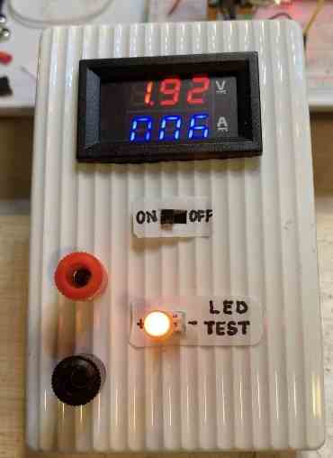
The following images were sent by Mr. V which show the test results measured across LEDs with various colors.
The first image shows the forward voltage drop of an amber colored LED, which is around 1.92 V.
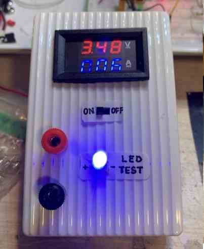
The second image below shows the forward voltage drop across a blue LED which is around 3.48 V.
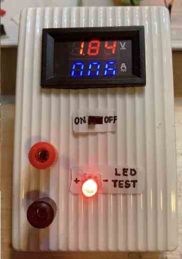
The third image below shows the forward voltage drop across a red LED which is around 1.84 V.
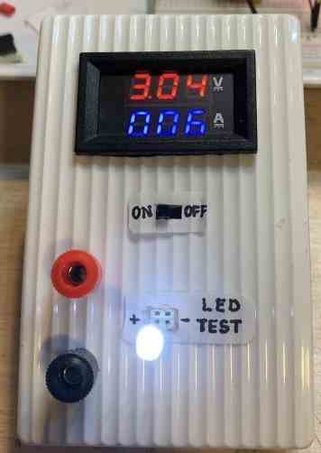
The fourth image below shows the forward voltage drop across a white LED which is around 3.04 V.

Need Help? Please Leave a Comment! We value your input—Kindly keep it relevant to the above topic!