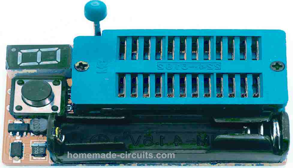
The IC Tester is simple to use. You don't have any switches to configure or lengthy test processes to complete. The universal IC Tester is a static tester, which means this does not dynamically test the IC's operation. All ICs with up to 20 pins can be tested by this unit. ICs with more than 20 pins can also be tested, however the testing will need to be performed off-board.
Basic Working theory
This tester design looks for PN junction errors in integrated circuits. Every integrated circuit is made up of diodes and transistors coupled in a variety of ways.
The PN connection on every pin, on the other hand, is shared by all ICs. When an IC malfunctions, one or more PN junctions tend to fail.
An integrated circuit's normal working can be disrupted or halted even if a single pn junction fails. Every integrated circuit has its very own semiconductive "signature," similar to how each human has a unique fingerprint.
The basic IC Tester shows a visual display of this fingerprint. When the "fingerprint" of the IC under test matches those of a known identical working IC, the IC may be considered to be in a good condition.
If the indicated fingerprints don't really match, the IC is deemed faulty. In most situations, the IC Tester will provide a fairly precise diagnosis of the chip being examined.
Twin rows of 10 LEDs reveal the IC markings. Each LED correlates to a separate IC pin. An IC's PN junctions are checked by first providing a positive voltage to the ground and/or +V pins.
This positive voltage subsequently activates the IC's forward biased PN connections. Using buffered circuitry, this forward current then turns ON the different LEDs on the pinout display. The intensity of the LEDs is determined by the number of PN connections and resistances in the current path of the integrated circuit.
Description of the circuit
The universal IC Tester is depicted schematically in the figure below. Each IC socket (SO1) pin is attached to a transistor buffer stage, which powers an indicator LED. Each pin connection in SO1 has 20 LEDs (LED1 to LED20).
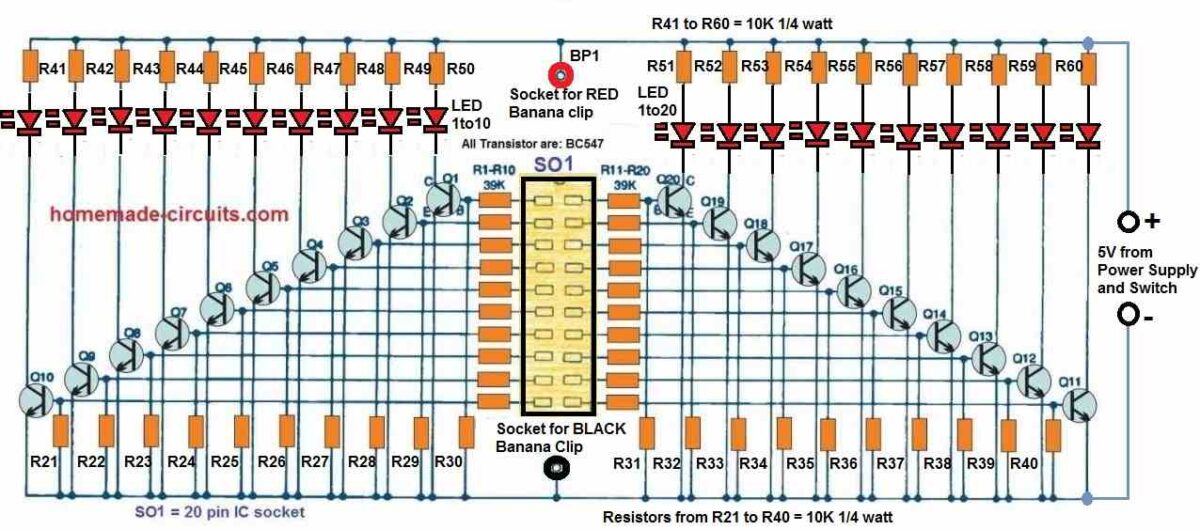
Buffering is provided by transistors Q1 to Q20, while current limiting, voltage division, and biasing are provided by resistors R1 to R20 and R21 to R40.
Initial Testing
It is essential to construct or acquire a 12-inch long test cable with a normal banana connector across one end and a micro crocodile clip on the other end, to initiate the IC tester operations.
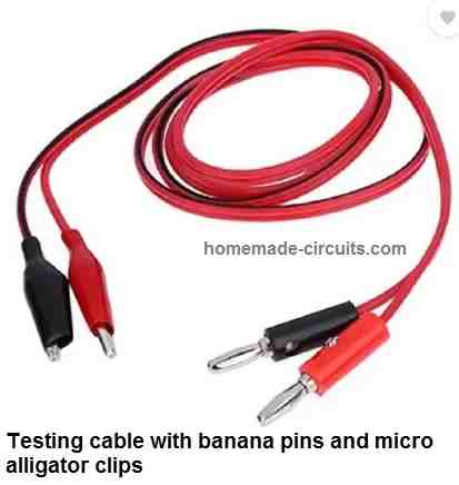
Although just one red wire is needed for regular tests, having a combination of one red and one black test cables is a better option.
Push the red cable's banana connector to BP1 connector, which is the red binding post.
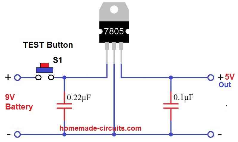
When the TEST pushbutton S1 is depressed, + 5-volts DC is applied to the small crocodile clip. Touch the end of the micro crocodile (metal hook) to each contact of the ZIF socket sequentially, while keeping S1 depressed.
In response to the above procedure, each of the corresponding LEDs associated with the SO1 pins will light up in succession, indicating that the tester is working correctly. Now it is ready to test ICs.
How to Test ICs
Push a known good IC into the ZIF socket to start the testing. Although it isn't important in which position you put the IC into the socket, you can utilize the pin orientation instructions on the front panel.
After the IC is installed into the socket, press the latch on the ZIF socket to secure the IC in place once it's in line. Now connect the alligator clip to the IC's ground or -V pin. If you don't remember the IC supply pins, you may have to look this up in a datasheet of the IC.
Press the TEST switch with the alligator clip in place and look at the ICs fingerprint on the LED display panel. If the IC is a digital chip, all of the LEDs must be illuminated with a certain level of brightness.
TTL and CMOS digital ICs may, in practice, illuminate all of the LEDs. We haven't found any exceptions yet, but you might. Of course, pins marked as "not connected" (NC) have no effect on the LED functioning.
If an attached pin on a digital IC somehow doesn't illuminate the associated LED, the IC may be defective and therefore should be scrapped or labelled appropriately.
The rules may vary slightly in case the IC under test is a linear IC. A good device's LEDs may or may not be illuminated. You may even find variations in fingerprints from various manufacturers on the same IC.
When comparing schematic designs of the 555 timer IC from different manufacturers, you'll find that they're not all the same.
The fingerprint of the device may vary as a result of these variations. Two tests may be required for analogue or linear ICs. Press the TEST button after attaching the alligator clip to the V pin.
Keep track of which LEDs are turned on, off, or dimmed. Then, with the test-lead alligator clip removed, connect it to the +V pin of the IC.
Press the TEST button to see which LEDs are illuminated, dimmed, or unlit once again. Both of these tests should be performed with reference to a known and healthy sample IC. As mentioned above, make a note of the manufacturer, part number, and LED states.
When evaluating any dubious equipment, compare the aforementioned records to the test results of the IC under test.
If the LEDs for the same IC exhibit a different pattern, the IC must be deemed faulty and scrapped. In most situations, if the LED pattern matches, the device may be considered OK.
The second test is generally the most helpful while testing linear ICs. A faulty IC will frequently clear the first test but fail the second test.
When evaluating linear or analogue ICs, certain general rules are useful. They are as follows:
- Good ICs usually will have illuminated LEDs on their output pins.
- Faulty IC's output pins might indicate very dimly lit or switched OFF LEDs.
- Input pins may show LEDs in the switched ON or OFF depending on the specific IC.
- Dual, triple, quad, and other function ICs should have exactly equal input and output pins. (For example, if one input pin of a dual op-amp shows an illuminated LED, the other input pin should be illuminated as well.)
Keeping track of your results through a reference library can be a wonderful idea.
You'll have to depend less on obtaining a known good IC for comparative testing as your library data increases. Instead, look up for the specific IC in your library and take note of what the output LED display should look like if the IC is working properly.
You can make note of your findings in any way you want, as long as you're consistent!
There's more You can do
There are many other things that can be tested with this multifunctional IC tester. You may use it to test diodes, transistors, inductors, and capacitors, among other things.
Diode Testing:
- Connect the diode leads to any two SO1 contacts.
- Hook up the anode lead to the positive alligator clip. Initiate the system by pressing the TEST button. If the diode is working properly, both LEDs must light up.
- Connect the cathode pin to the alligator clip.
Start testing by pressing the TEST button. Now, only the cathode LED must illuminate if indeed the diode is okay.
How to Test an NPN Transistors:
- Connect the transistor pins to any three of SO1's connections.
- Secure the alligator clip to the base pin of the transistor. If the device is working properly, the base, emitter, and collector LEDs should all be illuminated.
- Connect the emitter pin to the alligator clip.
- Now as you press the TEST button, the collector and base leads must NOT illuminate.
- Connect the collector lead to the alligator clip. Start testing by pressing the TEST button.
- If the NPN is working properly, the base and emitter LEDs must not illuminate.
Putting PNP Transistors to the Test:
- Connect the transistor pins to any three of SO1's ports.
- Secure the alligator clip to the transistor base pin. Initiate the system by pressing the TEST button. The LEDs in the emitter and collector must not be turned on.
- Hookup the collector pin to the alligator clip.
- When the TEST button is pressed, the emitter LED must not light up.
- Connect the emitter pin to the alligator clip. Perform testing by pressing the TEST button.
- The collector LED must be turned off.
Testing Inductors
- Connect the terminals of the inductor to any two SO1 connections.
- Connect any lead with an alligator clip.
- Start the system by pressing the TEST button.
- Both LEDs must turn on, with one of them perhaps being brighter than the other.
- The inductor may be open or might be with an extraordinarily high resistance if one of the LEDs is not illuminated.
Capacitor Testing:
This testing is only good for determining the general state of a capacitor, and it performs better with values higher than 1uF.
- Thoroughly discharge the capacitor. Connect the capacitor pins to any two SO1 connections.
- In case the capacitor is polarized, connect an alligator clip to the positive pin of the capacitor.
- Push the TEST button while keeping a close watch on the LED on the negative lead.
- The LED should blink just once for capacitors having minimal values.
- For bigger values, as the capacitor charges up, the LED will illuminate brightly first, then gradually fade away.
- The LED would not blink or illuminate if the capacitor is open.
- The LED will remain illuminated as long as the TEST button remains depressed if somehow the capacitor is shorted internally.
Wrapping up
For most technicians and enthusiasts, this universal IC tester circuit may be a very handy device.
Despite the fact that its indications are not always precise, this should correctly determine the state of numerous electronic parts.
The IC Tester is simple to operate and needs hardly any learning.
Simple CMOS IC Gate Checker Circuit
You have a variety of CMOS gates in your parts bin, but how do you know which one is which? Here is an easy checker.
Thankfully, normal quad gates are available in 14-pin packages.
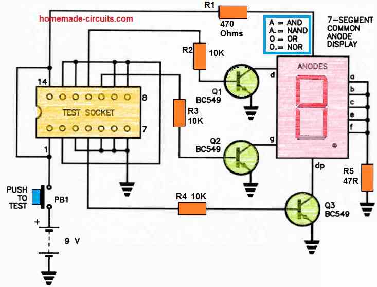
When you insert them into the test socket and hit PB1, the display will indicate what it is doing as follows:
- The letter 'A' denotes an AND gate package.
- 'A.' indicates that the item is a NAND gate package.
- If there is a '0', the package is an OR gate.
- The '0.' signifies that the package is a NOR gate.
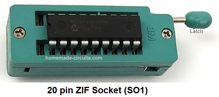
Use of a zero insertion force [ZIF] socket might be wise in this situation.


Comments
In this Simple CMOS IC Gate Checker Circuit, how are the inputs interconnected (in what way)? Also, how does the 10th pin receive power supply when an AND gate is inserted into the socket? Similarly, how does this work for other gates?
Hi,
I’ve found the schematic you used, exactly the same, in an Electronic Magazine of several years ago.
But in that magazine, I think there’s a lack of useful description.
I liked alot your description on the use of this circuit!
I think, as a worker in a repair center, that this schematic is still very, very VERY useful in troubleshooting.
While repairing, I test the IC (eighter Analog/digital) using the multimeter to test rach input / output protection diodes which is built inside every chip.
But several times this cannot be accoplished for the cicuitry around.
So is necessary to remove the chip and test it outside the board.
This is the reason I need this working device.
So I would like to have a complete info on the schematic.
I searched a lot and I found a problem: where is the S1 test button in the schematic?
Please can you help me?
Thanks
Regards
Mario Di Stefano
Thank you Mario,
I am glad you found the concept helpful.
The above article was contributed by another author so I have no information regarding from where this article was taken.
Also since this is not designed by me, providing more details or deeper explanation could be difficult for me.
As far as I can understand, the S1 is mistakenly not shown in the diagram. S1 must be in series with the +5V supply, so that when it is depressed the +5V is able to reach all the resistors connected with the LEDs and to BP1 socket which is supposed to be connected to the red crocodile clip.