A crystal radio circuit is probably the simplest form of radio that uses hardly any electronic components, and needs absolutely no external power for the operations.
Crystal Radio Concept
The only downside of this radio concept is the requirement of a very long antenna and a deep earthing, therefore this unit is not something which you can carry in your pocket. Nevertheless the extreme simplicity and the no power operation feature make this circuit an amazing device.
The main components involved with this simple crystal radio set circuit are an ordinary antenna coil, a detector diode, an optional resistor, and a crystal earphone. The detector diode could be any regular germanium diode such as OA91 or 1N34A etc.
Using Crystal Earphone
The received sound is best obtained over a crystal earphone. This type of earphone use piezo transducer and thereby ensure a high impedance across their input leads. Due to this high impedance, even the weakest of the signals in terms of current can be heard over this earphone by keeping the unit attached close to the ear.
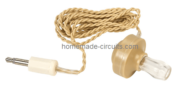
A crystal earphone is recommended here, due to its high impedance property, which makes it a voltage sensitive device rather than a current sensitive device.
Meaning the earphone would be able to transform even the weakest of voltage frequencies regardless of the current (mA) magnitude, enabling hearing of even the feeblest of the radio signals. This is crucial since no external power is being used for the amplification.
Typically a crystal earphone with a range of 2K ohms should be just good enough value for our crystal radio application.
To check the efficiency level of a crystal earphone, you could probably do a few simple but very interesting tests with it.
The first test could be performed by simply scratching the end terminals of its wires with each other, this should produce faint clicking sound in the earphone, another test can be tried by firmly holding the stripped ends of its wires and standing near your home mains line....this should enable you to hear a reasonably strong humming sound in the earphone.
These tests might be enough to convince you regarding the high level of sensitivity that these units may be specified with.
This high sensitivity of the crystal earphone along with the resonant tuning of the radio's LC tank circuit stage, together ensures a sound level that's loud enough to be clearly heard without using any form of external power supply.
With no external power, the weak electrical pulses of the radio signal is itself processed and used by the crystal circuit and the crystal earphone and is made efficiently audible in our ears.
This radio can be used for hearing local stations at around 50kms range during daytime and from over 100 of miles away at night when the surrounding noise is much reduced compared to the daytime commotion.
The key element that helps the crystal set to grab even the minutest of radio reception is the length of the antenna used, it should be preferably a 30to 40 meter long flexible wire suitably tied and hung at some elevation such as a tree branch etc.
The antenna will be capable of capturing quite many radio stations including the night time DX stations, due to the favorable ionosphere transition after the sun goes down.
The second crucial element of the design is the "earthing" or the ground quality, which should not be ignored otherwise the radio could simply refuse to provide the intended results.
A Good Earthing is Crucial
A perfect ground can be achieved by inserting a steel rod deep into a 5 feet hole dug on earth which should be first adequately watered to make it soft and then a bag of salt thrown into it to make things sufficiently conductive, and for creating an efficient grounding for the circuit.
Another easy method for achieving the earthing is by using the tap or the metallic plumbing line of your bathroom which also would act as a very good earthing for the circuit.
Circuit Operation
Once the above mentioned antenna and the earthing is correctly set up, it's time to connect the simple crystal radio circuit with these parameters.
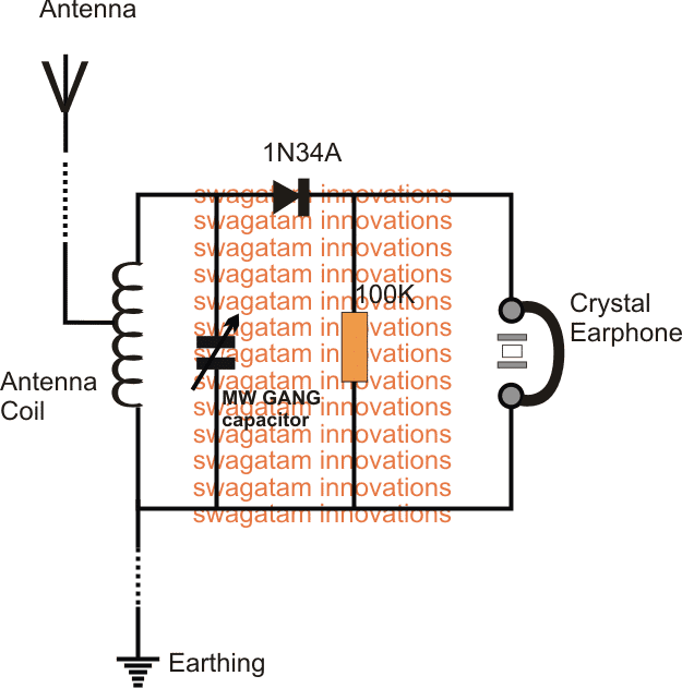
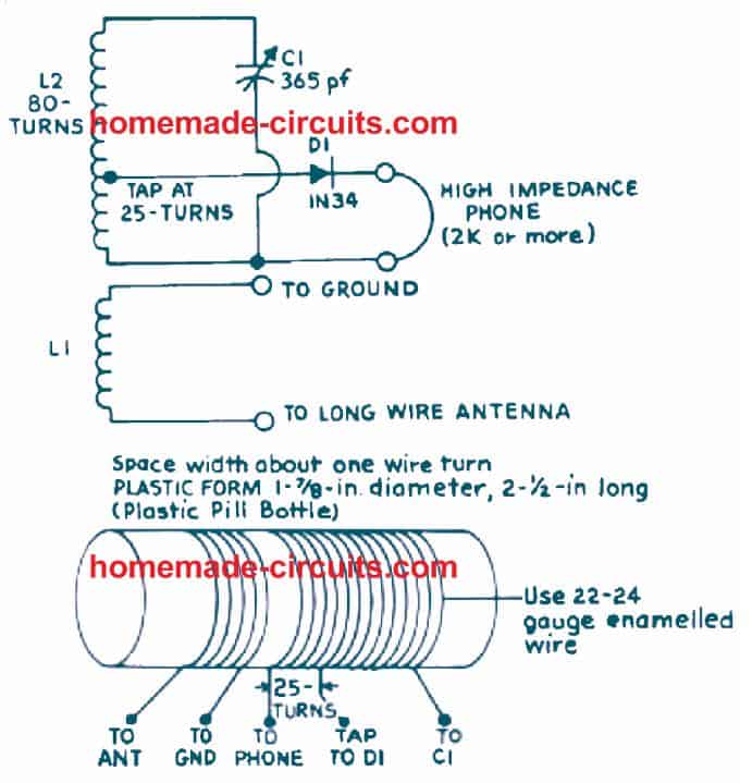
Referring to the figure above, we see that the circuit hardly comprises any serious parts, it uses one antenna coil made by winding many turns of thin copper wire over a plastic bobbin with three wire ends terminating outwards, wherein the mid tap is used for the antenna connection.
The resonant tank circuit is formed by connecting a trimmer parallel to the antenna coil ends, this trimmer could be any MW GANG capacitor, again the same could be salvaged from any old radio set.
The radio signals are picked and resonated to the peak level through this tank circuit network, however in order to detect and demodulate the sound from the signal's carrier waves we need another stage for this function.
An ordinary germanium diode is what we need to carry out the detection work and it does this quite effectively. Even our very familiar silicon 1N4148 could be tried for the job but only in case you are unable to procure the regular OA91 or the IN34A type of devices. And this part is the only active component involved in the whole circuit for reproducing the original sound from the captured signals, that's amazing.
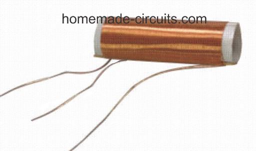
How to Wind the Antenna Coil:
The antenna coil is an air cored winding, it's built with the following simple steps:
You will need a 1 or 1.5 inch diameter, and 4 inches long plastic pipe for the bobbin.
Over this pipe wind some 65 turns of any thin super enameled copper wire or any thin insulated flexible wire such as a 7/36 multi strand insulated wire.
Make sure to pull out a center tap at around 18th turn of the winding, or some other number tap can also experimented with for trying preferred customized receptions.
That's all, the antenna coil is ready and may be used for the above explained simple crystal radio circuit.
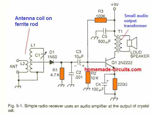
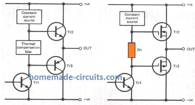
Adding an Audio Amplifier (Learn More)
If you want to add a loudspeaker to the crystal et above, you can simply do it by integrating a small audio amplifier to the crystal set as shown below:
If you have any questions or doubts, don't hesitate to put it forth through comments below.
Pictorial Details of a Crystal Set
- C1 - 365-pF variable tuning capacitor
- D1 - 1N34 germanium diode, or any other germanium signal diode
- L1 - 25 number of turns of #22 or #24 enameled copper wire firmly wound on a 1 and 7/8 in. form.
- L2 - 80 number of turns of #22 or #24 enameled copper wire having a tap at 25th turn closest to the coil L1 on same former on which coil L1 is wound.
- 1 - High-impedance headphone


Comments
thanks indeed of radio fm & am circuits
thanks, glad you liked them.
How much amperage is passing through the simple version of this circuit which does not have the audio amplification from a 9V battery?
Can’t say how much, I have not measured it.
Would the effect be the same if I used a standalone electromagnetic transducer with leads (one intended for through-hole mounting) as opposed to a crystal earphone?
I am not sure about it, you can give it a try, might just work…
Can you specify how to solve inductor, capacitor values for receiving specific frequency like say 630 KHz. Thanks ^_^
sory I do not have the calculations for this simple radio design
But do you have an idea? coz I cant find much on the internet.. 🙁
you can try it yourself by some trial and error. The coil turns can be simply tweaked to achieve the results
Sir ,
I want to make a remote control fan that run forward or back as I want . The range is about 500m long to catch the signal from remote .
I want this type of circuit and I hope the use of crystal is best in this circuit .
Mayank, you mean you need the oscillator for a transmitter circuit?
but along with the oscillator an amplifier circuit will also be required and it can be a significantly large circuit for a 500m range…I do not have this circuit at the moment, if i find I will let you know
Hello sir ,
I want to make a crystal oscillator circuit using transistor or MOSFET . Can you please help me.
Thanks
Hello Mayank, yes I can help, can you please specify the application need of the circuit…meaning for what purpose you need the circuit?