In this post I have explained the pinout assignments and functions of the popular 433 MHz RF remote control module from HOLTEK.
RF 315 MHz / 433 MHz Transmitter-receiver Module for Remote Control Application
Making your own universal remote control systems today is very easy.
Such procure the relevant chips, assemble them and here goes, your hi-tech remote control device is working for you.
Here we explain a couple of RF 433MHz remote control chips especially designed for the purpose.
The IC TWS-434 along with its encoder chip HOLTEK’s HT-12E form a high class transmitter circuit.
The chip RWS-434 through its complementing decoder IC HT-12D operates as the receiver module.
Both of the above modules are able to exchange 4-bits of discrete data for control four external loads separately.
With the easy availability of accurate remote control chips, making your own universal remote control modules is today just a matter of few hours.
We discuss a couple of compact RF remote control transmitter and receiver modules here using the chips: HT-12E, HT-12D, TWS-434, RWS-434
Making a hi-end professional remote control system at home is a child’s play now. With the advent of micro remote control encoder and decoders chips, making a RF remote control is today a matter of a few hours or rather minutes.
Applications of remote controls made from these chips are countless; you may use it for controlling practically any electrical gadget that you can think of, the best application being for car security systems.
TWS-434 and RWS-434
A couple of RF remote control chips, the TWS-434 and the RWS-434 both complement each other, the first one being the transmitter and the later one the receiver.
The chip TWS-434 is basically a tiny 4-bit transmitter module, which is able to transmit 4 types of coded signals discretely, whereas the RWS-434 exactly complements these signals by receiving them and generating 4 discrete decoded signals at its outputs.
However both the above primarily functions just as wireless sender and receiver and therefore require external encoders and decoders to be integrated for the said operations.
Understanding the 433MHz RF Transmitter Module Pinouts
A couple of HOLTEK’s encoder and decoder chips HT-12E and HT-12D work in conjunction with TWS-434 and RWS-434 respectively to produce the desired ideal universal remote control operating parameters.
Referring to the diagram alongside, we find a straightforward RF transmitter configuration using the chip TWS-434 and HT-12E.
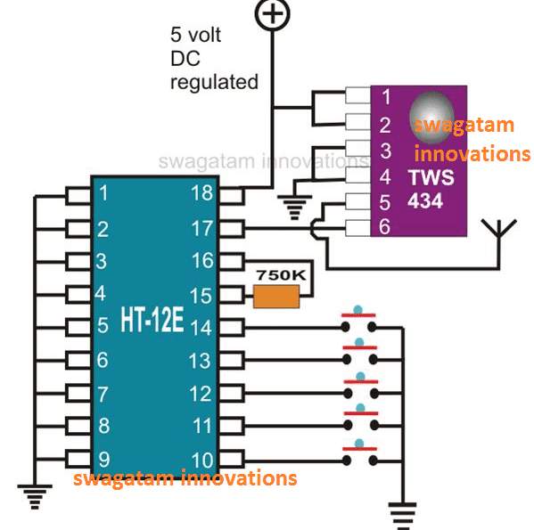
The IC TWS-434 has in all 6 pin outs, 1 and 2 are the positive inputs, 3 and 4 are to be grounded, 6 receives the 4-bit encoded signals, pin 5 being the antenna for radiating the received signals.
The pinout details of the RF transmitter as shown in the above diagram may be understood as follows:
The 4-bit encoding is done by the IC HT-12E.
The wiring of this IC is also very simple; all its 1 to 9 pin-outs are shorted together to ground and these refer to the address pinouts of the IC.
These 1 to 9 address pins can be configured differently as desired to generate a variety of different encoded messages from the transmitter.
For example, you can leave a 1 to 4 pins unconnected and connect the remaining pins to ground, this will produce a differently encoded output signals which will be completely different from the one where all the pins are connected to ground.
In this way you can generate many different sets of unique configurations by selecting any desired 1 to 9 pins either left open or connected to ground.
Thus, you can create different variations with these 1 to 9 pins, some of them connected to ground and some of them not connected to ground, or all of them connected to ground.
Remember, the connection pattern created across pins 1 to 9 in the transmitter circuit must be exactly replicated in the receiver circuit, otherwise the two units will not be compatible and will fail to work together.
Pin 16 and 15 are coupled to each other through a 750 K resistor.
Pinouts 10, 11, 12, 13, all receive 4 discrete data simply through the connections of the respective pins to ground via a push button switch.
Pin 14 confirms switching of the transmitter signals when connected to ground via another push button.
Pin 17 is the output and conveys the processed 4-bit ata to the IC TWS-434 for the final relay. Pin 18 is for the positive supply input
Understanding the 433MHz RF Receiver Module Pinouts
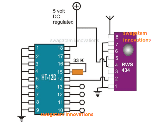
The diagram alongside shows a similar configuration to the above, but with exactly the opposite transits.
The pinout specifications for the RF receiver module as shown above may be understood from the following explanation:
Here, the chip RWS-434,s antenna receive the data transmitted by the above transmitter module and sends it to the IC HT-12D for the necessary decoding of the 4-bit data which ultimately is decoded and produced at the respective outputs for driving the connected loads.
Understanding the pin-outs of the IC RSW-434 is pretty simple, pin 1, 6 and 7 are all shorted to ground.
Pin 4, 5 go to the positive supply.
Pin 2 outputs the received data to the decoder IC and pin 8 serves as the antenna.
The decoder chip HT-12D has its entire pin from 1 to 9 fixed to the ground potential.
Pin 15 is connected to 16 through a 33 K resistor as per its specs.
Pin 14 receives the information received by RSW-434 and after decoding the processed data is obtained from the pins 10, 11, 12, 13 respectively, which is further fed to the output driving circuit for activating the connected gadgets.
Both the modules of the above universal remote control work satisfactorily through a regulated 5 volt power supply unit.
If you have any specific questions regarding the pinouts of the above explained 433 MHz RF transmitter and receiver modules please feel free to ask them through your comments.


Comments
Dear sir..may I know which software did you use to make schematic circuit? I always use proteus..but some components are not available in that software..and I want to run a circuit simulation..please help me again..thank you and waiting for your reply soon..:)
Dear Akmar, I usually simulate the circuits in my mind, I don't use any software, so not sure about them.
Hi, I'm making a similar circuit but I have a little problem I bought two pairs of the rf circuits, I mean 2 transmitter and 2 receiver in order to have 8 devices to controlled, but when I did the first circuits (receiver and transmitter) they worked properly, but when I did another pair of circuits (receiver and transmitter), the first circuits stop working, actually they work if I don't connect the second circuits and the second circuits work if I don't connect the first circuits, what could I do?, both circuits have a different address
yes, you can try doing it if you know how to it.
could I change the frequency? , both remotes are in 434Mhz frequency
Hi, It's difficult to figure out, they might be operating with the same frequencies but in that case all should have worked randomly irrespective of whether remote#1 or remote#2 is being used, but in your case one is blocking the other, I have played with many such circuits but haven't faced this problem yet, so really can't troubleshoot the issue.
Thank you
Will it be secure what if another person would build the same circuit will that person be able to control the output What can i do to make more personalize like the remote for the car alarm. Can i used a dual tone multiple frequency encoder decoder with the transmitter
The possibility can be eliminated by configuring the address pins uniquely for the particular Rx/Tx sets.
Suppose you disconnect all the address pins A1 to A10 of the Rx module and select A1 and A2 only for the ground connections, and you do the same with the Tx module….this will make the two unit compatible and paired with each other uniquely and will not respond to other modules in the vicinity which could have a different address pin configuration.
In this way you can select different sets of address pins and group them with each other or with ground (identically for both the modules) for creating unique pairs.
the outputs are four only, the extra pins are unused or are shorted.