In this post I have explained how to interface a 4x4 keypad with Arduino. We are going to see what is a keypad, how it is constructed and a how to program the Arduino to receive keystrokes form the keypad and print them in serial monitor.
What is a keypad?
A keypad is a portable keyboard in small form factor with sets of numbers, alphabets and special characters or combination of all three. In this project we are going to take a look at 4x4 matrix keyboard which has all the three types of keys specified above.
It is called 4x4 because it has 4 rows and 4 columns, arranged in matrix form. It has numbers from 0 to 9, special character “#” and “*” and alphabets from A to D. There are other types of keypad like 4x3, 8x8 etc. The most common types are 4x4 and 4x3.
For 4x4 keypad, four connections from rows and four connections columns are made for communicating with microcontroller, so totally there are 8 pins.
This may consume lots of I/O pins from Arduino and leave less number of I/O pins for other peripherals, there other methods to receive keystrokes by utilizing few pins of Arduino, which are not covered in this article.
Construction Details:
The connection circuit is illustrated below:
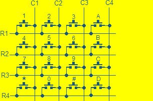
As we can infer from the above diagram, each keys are connected to one row and one column. When any one of them are depressed, for instance number 1, R1 and C1 gets connected, this signal will be received by arduino or any microcontroller and determine which key is pressed, for each key, unique connections are made.
We can get 4x4 keypad from e-commerce website or local electronics retailer or you can make one from the diagram above. You just need 16 push buttons for 4x4 keypad and a general purpose PCB. The connections can be made from the above diagram and you made one for yourself.
Arduino Keypad circuit diagram and program:
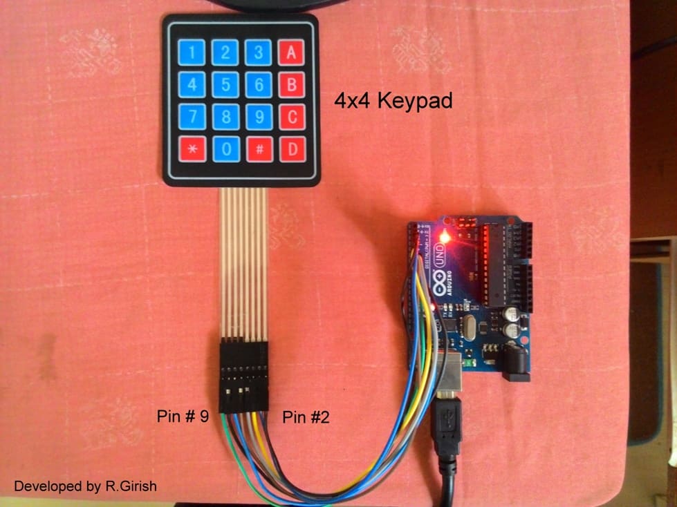
Here is a prototype, where connections are made by using male to male header pins. The rest of the circuit is self explanatory.
Here's how it is connected to Arduino:
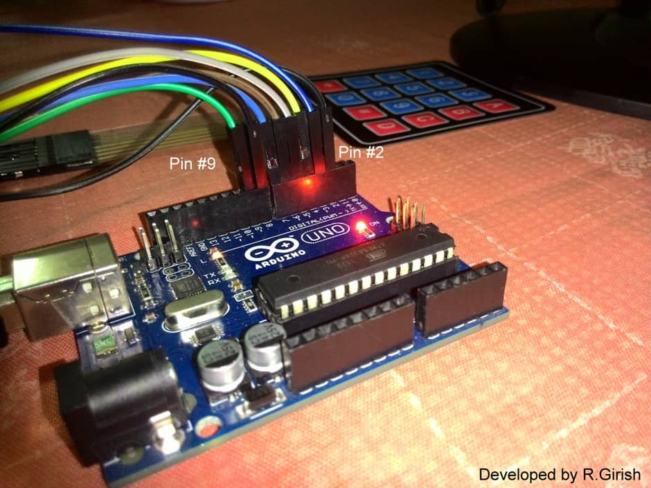
Note: care should be taken while connecting the pins from keypad to arduino, any improper connections or any wires interchanged, it can mess your whole project.
All the connections are made sequentially from pin #2 to pin #9 of Arduino and keypad. That’s all about hardware connections now let’s move to coding part.
Program Code:
//---------------Program developed by R.Girish------//

#include <Keypad.h>

const byte ROWS = 4;

const byte COLS = 4;

char keys[ROWS][COLS] =

{

{'1', '2', '3', 'A'},

{'4', '5', '6', 'B'},

{'7', '8', '9', 'C'},

{'*', '0', '#', 'D'}

};

byte rowPins[ROWS] = {9,8,7,6};

byte colPins[COLS]= {5,4,3,2};

Keypad keypad = Keypad( makeKeymap(keys), rowPins, colPins, ROWS, COLS );

void setup(){

Serial.begin(9600);

}

void loop(){

char key = keypad.waitForKey();

delay(100);

Serial.print("You pressed: ");

Serial.println(key);

}

//---------------Program developed by R.Girish------//
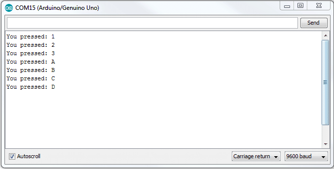
Output:
Using the Keypad
In the program two dimensional array concept is utilized, as we can see the same layout is made in the program as in the keypad. The row pins are 9, 8, 7, 6 and the pins columns are 5, 4, 3, and 2.
We used a line “char key = keypad.waitForKey();” which means the programs will wait for a key to be pressed and the depressed key will get stored in a variable ‘key’. This variable is printed in the serial monitor using “Serial.print();.
If you are wondering where keypads are used? Well, here is the answer. It is used everywhere, where a user need to give input to any machine for example: the Smartphone or the computer you are using right now, ATM machines, vending machines, printers, controls on your TV remote etc.
By now, you know quite a bit about keypads and how to interface them with an Arduino, now it’s time to use your imagination to build your own projects.
You need to download and add the keypad library from the following link: github.com/Chris--A/Keypad . otherwise the above program won't compile

Questions & Answers
Hi davis,
I am going to do something similar for the upcoming articles. so, stay tuned….
Regards
its nice . now my request is how can i go about coding using arduino and that keypad to make a password door lock en unlock through pressing those digits on keypad , which makes a door open when certain digits a pressed and closes when other digits are pressed. great thanks