In this post I have explained a simple mosquito electrocution net, or mesh circuit which can be easily built and installed on a home window for blocking and killing an in-surge of mosquitoes. The idea was requested by Mr. Ram.
Technical Specifications
Please help with any working circuit diagram for Mosquito, Insect Killer using Walton Voltage multiplier method. Output should be around 2kv. I want to let it remain connected in ac mains like 'Insect Killer cum Night Lamp' which are available on market but they are having 900-1000v in output and stop working in few days.
I tried to get help from Google but I am getting negative feedback most of the time. People are saying they are getting dropped voltage at output. You have some circuits, but they are battery operated and can't remain on all the times.
Please help with with a new topic on this format.
Regards
Ram
The Design
Warning: The circuit design explained below involves a very high voltage, extreme caution is advised while testing and using the unit for the application.
In one of the earlier posts we discovered how conventional mosquitoes traps work by luring the insects through the generation of CO2 gas (by burning propane gas), and other other forms of agents such as octenol which imitate human respiration and human body odor respectively, and help to attract mosquitoes towards these artificially generated baits.
However since there's no easy way of manufacturing CO2 at home, neither is acquiring octenol for the same, attracting mosquitoes the usual way looks to be the most hassle free option.
The natural way is the manner in which we find the mosquitoes enter our houses everyday in the evening, by tracking the CO2 content generating by us in our house and also by the body odor that may be consistently present inside our homes.
Also since the entry path of the mosquitoes is usually through the windows, this entrance can be effectively used for installing a trap and for killing the insects.
The idea here is to position a set of steel meshes covering a particular selected window, and powered with a high voltage source. When the mosquitoes try to make their way through this window, they are instantly killed through electrocution between the mesh structures.
I have already discussed the mechanism and a working circuit of a mosquito zapper bat in one of my previous posts, which utilized a high voltage generator for electrocuting the insects trapped in the bat mesh. The present mosquito killer design is also based on the same principle and makes use of a high voltage across a window mesh for electrocuting the passing mosquitoes.
In one of the other posts I have explained how to make a CDI driver circuit for generating high voltage sparks inside a vehicle spark plug.
Since the above concept facilitates an easy and quick way of implementing a high voltage across a given pair of terminals, we incorporate the same for creating the electrocuting arcs across a set of window mesh assemblies.
The following discussion shows how the mosquito trap or the mosquito killer mesh can be built at home for the suggested purpose.
Designing the Steel Mesh
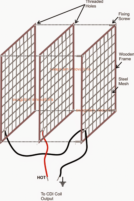
Referring to the shown diagram the mesh assembly is built by fitting three identical sets of readymade fine iron or steel nets with a help of a few well fabricated square wooden frames.
After securing the steel nets within the wooden frames, these are tightly screwed together face to face using nuts and bolts and spacers such that the three frames acquire an optimized distance from each other.
The above assembly actually becomes the most tedious and the crucial part of the system and once this is completed, making the high voltage mosquito killer circuit can be rather simply done with the help of the following circuit.
The High Voltage Generator Circuit
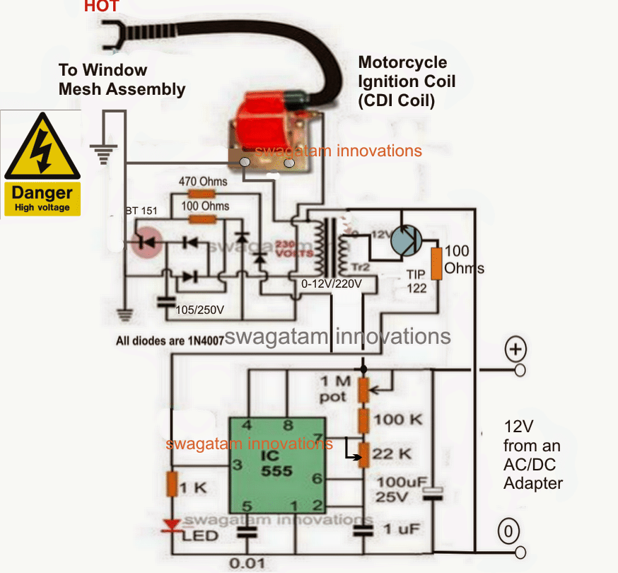
In the above high voltage generator circuit, the IC 555 astable is used for feeding high frequency pulses to the primary of an ordinary 0-12V/220V transformer, via a switching transistor TIP122.
This generates the specified 220V across the other side of the transformer which is used for charging a high voltage capacitor via a network of rectifier diodes.
The accumulated 220V charge inside the capacitor is alternately discharged by an SCR circuit, such that the discharge voltage is dumped across the primary of a standard ignition coil transformer, commonly seen in motorcycles for generating sparks in the spark plug.
The induced 220V in the primary of the ignition coil generates a very high voltage across its secondary high tension wire.
This extremely high voltage is fed across the steel mesh, in the manner as specified in the first diagram.
The central mesh carries the hot end of the ignition coil, while the outer meshes are connected with the ground potential of the circuit.
The 22k of the 555 IC circuit is carefully adjusted such that the sparks do not fly off between meshes as long as there are no interfering elements between the meshes, but trigger thee sparks as soon as a "fly" or a mosquito is detected between the mesh assemblies.
The 100k pot must be used to regulate and produce the best frequency which may ensure reasonably cool running of the two transformers.
The circuit may be powered with any standard 0-12V/1amp adapter unit.
Comments
respected sir Ihave gone through your above circuit with due respect.
can we use tv eht. from older scrapcircuit.
pl kindly post a circuit with the component details and winding details to build a home made racket and how much vbatus required for racket. with sutocut charging circuit. I would like you to send me sutocut charging circuit with diagram and components list in my email Shruti 7697@gmail .com pl share your contact number and email it’s really nice if you for your website it’s helpful to hobbyist and students.
Hello Mukund,
Yes, TV EHT can be configured for getting the intended high voltage output.
I already have a mosquito swatter racket circuit explained in the following article, you can check it out:
https://www.homemade-circuits.com/mosquito-swatter-bat-circuit/
However, to make a 100% working circuit I would recommend you to open a commercial mosquito racket and reverse-engineer the whole circuit and get the exact details of all the components and the transformer winding data.
The 220 volt primary leg of the transformer has a blocking diode to ground- not needed-if it fails, you have a fault to ground! If the SCR conducts,you also have a fault to ground.
I would like to scale up this design to 1.5×2 meters mesh.
Are there any alteration that need to be made?
Also, can I use an electric zapper circuite that I have disassmbeled to speed things up?
You can do that, you can use the same circuit design explained above without any changes. If your electric zapper is powerful enough, you can try that also…
Dear sir
can i apply the mosquito killer in commercial purpose ? any consent required this case I’m agree yours terms and conditions for this ckt use commercial purpose or any update ckt about this type which more efficient and robust for commercial purpose. please help me and wait for your feed back.
Hello Biswajit,
You can use this circuit to manufacture commercial products without any consent. But remember since this circuit generates high voltage electricity the risks involved with this circuit will be your responsibility, so please do it at your own risks.
Dear Sir agricultural use
Hi GV, please elaborate your question…
Thank you for headind . I think everyday when somebody think same me .
I will read and try to do follow you.
Every one is talking abt the circuit… no one is talking abt the mesh part. You have also NOT given any design details of it.. or tips…
size of the square in the mesh
Do we need spacer of what size.
how much is the distance between the 2
these technical details or any more which you like to share
The mesh net holes must be 2 to 3 square mm rectangles using 1mm thick steel wires, and the three nets must be fixed at a distance of around 2mm to 3mm apart from each other using spacers.
Hi Swagatam, May I use just 2 nets? what is the effect? I will just be using high voltage transformer – 110V/3500V with 9mA rating. Is this ok? should I reduce the voltage of transformer? or may I increase the 9mA rating of the wire. Also, how do I minimize the risk of ionizing the air enough that it will cause spark even when there is no mosquito in between? lower the voltage? etc..etc. Thank you very much.
Hi kknight,
Just 100V is enough to kill a mosquito, but in that case the mosquito will need to bridge across the high voltage terminals or across the two meshes. If the mosquito is not bridging the two mesh wires then the mosquito may not be electrocuted with 100V.
In order to ensue that the mosquito gets electrocuted even without bridging the mesh wires we need a voltage that would create an arcing across the mosquito and the mesh, which might require the voltage to be at least around 2000 volts.
The transformer you have mentioned looks perfect for the current application, you can use it without any modifications.
To avoid sparking in the idle mode you can arrange the mesh distance to an optimal distance which may be far enough to prevent unwanted sparking.
ok. so I can try the 110VAC and just put the 2 meshes near each other around 3mm.Since it it too low a voltage, I wont worry with the arcing or ionizing the air. Since a mosquito is around 3mm and above length, im pretty sure that it will bridge or short out the 2 meshes and electrocute the mosquitoes. May I know what are the risks if I lower down to this voltage 110V, as compared to using the 2000 volts and above setup? Thank you for your help. 🙂
110V AC from an AC outlet can have lethal high current, that is why is not recommended. However, you can drop the current by adding series capacitors in series with the phase and the neutral lines individually. The capacitor can be a 0.1uF/400V capacitor. So it is a feasible option, but please do it by considering the dangers of using AC mains involved in the system.
If you use two nets instead of three, one of the LIVE wires may remain exposed and be susceptible to human contact and fatal electric shocks….
alright. But since I will be using High voltage AC, then 3 meshes would just be the same, the outer meshes are still live ACs. Thank you Swagatam!
The outer meshes are not LIVE, the center mesh has the LIVE connection. The outer meshes are cold, the center mesh is the Hot one.
Is it advisable to use aluminum or stainless steel? If I use a high voltage transformer, what is the suggested Voltage AC and current limit to effectively electrocute the mosquitoes and not damaging the transformer or related circuitry? thank you.
Both, stainless steel or aluminum can work. The minimum voltage can be around 2kv.
Ok, thanks vmuch Swagatam!:)
Hi swagatam I want to make a mosquito insect killer using two diodes and two capacitors can you help me ?
Hi Mustafa, that may not be possible, instead you can try this concept
https://www.homemade-circuits.com/mosquito-bat-without-battery/
PLEASE LET MI KNOW TRANSFORMER PART NO.
Transformer is 0-12V/220V.
Thank you, i made circuit and it working do thank you again.
I also request for please make electrostatic circuit for agricultural sparying.
I am glad it worked, I’ll surely investigate the mentioned concept and try to include it in my website as soon as possible.
Ok, thank you, please try i am farm if u Success i also help other farmers
sure, I’ll let you know!
Above circuit i use 0.01uf as 103/50v non non polorised is it correct?
I can not get BT151 any eqvalant ?
you can try C106
I make above circuit , but led not blinking and on cdi coil one time spark wwhat happened sir ?
Please refer to the last diagram as given in the following article and build it accordingly:
https://www.homemade-circuits.com/make-this-enhanced-capacitive-discharge/
Hiiii
This circuit is very usefull
SIR Swagatam Good afternoon,
You are the best and best man I have ever seen in the world, You care all your students and others in depth, Sir I really appreciate You always.
Sir I need a circuit of CCTV camera,
DESCRIPTION:-
If someone have ammunition then our CCTV camera would indicate or alarm the spider.
I need this circuit for protecting our city.
Sir I will wait for your reply
Best Regards
God Bless You
Thank you very much Arif, I appreciate your thoughts very much!
A CCTV camera circuit can be quite sophisticated and difficult to accomplish at home unless you have the entire kit and all the sophisticated gadgets for testing it.
Moreover identifying ammunition might require very sensitive metal detectors or X-ray cameras…all these are beyond my range of expertise….so I am sorry I don't think I would be able to help with this design.
I am really thankful for such a valueable post.
you are welcome!
I REALLY dig this, hope i muster up the balls to actualy build it. I've not done custom electronics for ages now (and then it was the simple ones), and it will be a task 🙂
I wish you all the best, I am sure you will succeed with this project:)
Sir we could not find unpolarized capacitors for the circuit and could only find polarized ones will our circuit still work or would have to make any changes?
105 is not the actual value, it's a code.
105 = 10,00000 pF = 1000 nF = 1uF
therefore 105 = 1uF
Should the capacitor be exactly be 105 uF or can its value be a little different like 100 uF or 120 uF?
Mubasher, the 105/400V must be non-polarized, other two can be polarized type.
Sir how do we set the value for 1M pot and what is its function?
after fabricating and fixing the net assembly you can carefully adjust the two pots such that the sparks do not fly across the nets in a normal condition… unless bridged with some kind of conducting material
Sir Can you please list all the components used in this circuit as the image is not clear
Please click on the diagram to enlarge it, you will be able to see all the parts clearly