In this post I have explained an innovative circuit modification which allows a single common lamp to be used as a parking light, turn signal indicator light, as well as a side marker light on the relevant positions. The idea was requested by Mr. Chris
Technical Specifications
I have a project that is slightly related to this one and could use your help.
I have 2 single filament bulbs that I would like to use as parking lights as well as turn signals.
They would be wired to stay on anytime the car is running, and each light would turn off and on when the corresponding turn signal is activated.
The wire from factory the turn signal harness controls the +12 side. I also have 2 single filament bulbs that I would like to use as side markers anytime the parking lights are on, and I want them to flash opposite the turn signal, so when the turn signal bulb is lit the side marker is off, and when the turn signal bulb is not lit, the side marker bulb is.
The side markers will not be lit unless the parking lights are on, but I do still want them to flash anytime the turn signals are activated. I prefer not to use led's as my project is striving for a retro look, but I might if it's not possible with the incandescent bulbs.
The Design
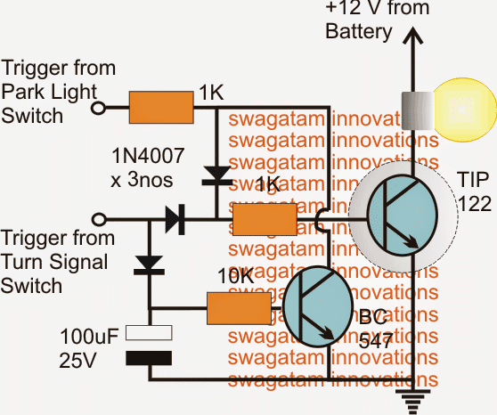
According to the first requirement a single lamp needs to perform the dual function of a turn signal lamp as well as a park light, also the lamp should switch ON as soon as the turn signal switch is turned ON.
The following modified turn signal cum park lamp implements the features exactly as per the above specs.
When the park light is in switched ON position, the TIP122 switches ON the lamp through its base trigger via the upper diode and the series 1K resistor.
Now, if the turn signal switch is triggered, the TIP122 responds by flashing the lamp, while the lower BC547 transistor which also gets triggered with the turn signals makes sure that the signal received from the park light switch is grounded and inhibited from influencing the lamp.
The second requirement demands another lamp which may be positioned as a side marker lamp to respond to the above side indicator or the turn signals but flash with an opposite switching. Also the same lamp is also supposed to light up when the park lights are ON.
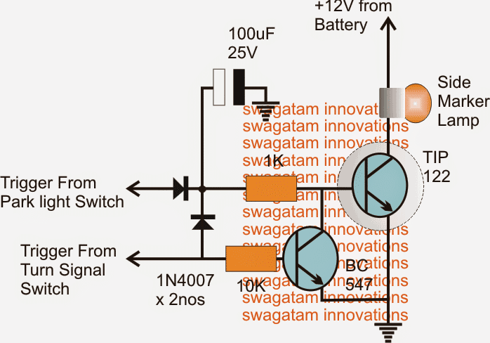
The diagram of the enhanced or the modified side marker lamp as shown above satisfies the conditions by flashing the connected lamp with opposite switching, and also responds to the parking switch toggling during normal operations.
The TIP122 is responsible for triggering the lamp when the park lights are switch in.
However when the turn signal switch is toggled, irrespective of the park light input the BC547 begins oscillating in response to the turn flash signals causing the TIP122 to also blink the lamp with the corresponding flash rate.
The 100uF capacitor makes sure that the TIP122 is fed with its stored positive feed for sustaining the illumination on the bulb during the flashing actions.
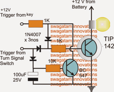
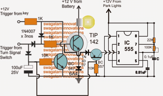
As per the suggestions from Mr. Chris, the first diagram has been slightly modified with the following couple of improvements:
1) The transistor has been upgraded to TIP142.
2) The park-light input trigger has been replaced with +12V trigger from the ignition key so that the lamp works as fog lights and not as parking lights.
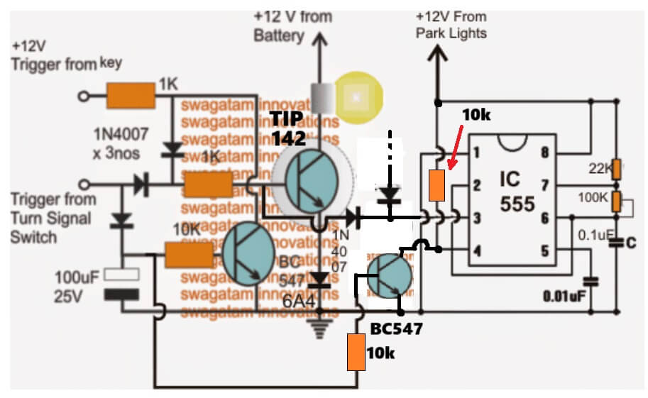
The above circuit could be enhanced further by adding a PWM dimming control feature as shown below. The feature enables dimming of the fog lights when the park lights are turned ON, but ensures that the effect is inhibited as soon as the turn signals are switched ON.
The 100k preset could be set appropriately for achieving the desired reduction in the fog light illumination


Comments (53)
Hello,
I have a question.
Considering the first circuit, which uses the same bulb for the parking and turn signal, would it be possible for it to be dimmed to 50% in parking light mode and blink from 0 to 100% when signaling (turn signal)?
Hi, sure…you can do it by increasing the topmost 1K resistor value to a higher level, such as to 68K or 100K etc…
Can the circuit get very hot? Should I be concerned about the installation location?
It will depend on the lamp wattage. If you use an LED lamp then the heat dissipation would be minimal…If the bulb is an older incandescent type filament bulb then the transistor can heat up quite a lot….
Ok, i will check.
In my case, the car’s original circuit uses a 25W incandescent bulb. The turn signal relay uses a current source.
Sure, no problem…but 25 watt is huge and will make the TIP27 red hot.
In that case I would recommend using a TIP35 but that will also require the middle 1k (just above the 10k) to be around 20 ohms or so…
If you can replace the 25 watt bulb with a 5 watt LED bulb that could keep things much cooler.
So I should replace the flasher relay, because the current will make it flash quickly.
Yes, you can replace it with an electronic flasher, whose flashing rate is not dependent on load…..
PWM works!
Here are some of the things I had to change…
1. Swapped the capacitor values on pin 6 and pin 5 on the 555. if the values are as indicated in the diagram, the dimming flashes more than it stays a stead dim. But with 0.1uF on pin 5 and 0.01uF on pin 2/6 it works perfectly.
2. Had to change the trimpot to 1M. 100K would not work at all.
3. Had to use two diodes between pin 7 (one reversed) and each end of the trim pot and only the wiper is connected to pin 6. I couldn’t get it to work as shown in this diagram, but it works great with the diodes etc.
4. I think you need a 3 pin flasher relay. A 2 pin relay will not work. Awaiting parts to test that part.
5. Going to use a smaller NPN darlington since my LED draws a max of 3W. Do you have a suggestion for a part number? I was thinking MJD122-1… it can handle upto 20W which should be plenty. (I need to make this circuit as compact as possible)
6. Is there a way to use one PWM controller to control the brightness on two of these circuits so I can use one trimpot to make both lights equally bright/dim?
Sounds great! Glad you could solve the PWM issue…
Yes the flasher output must be independent of the load, only then it will work without any issues..
You can replicate the PWM output stage through another LED driver transistor stage to control its brightness simultaneously.
There’s one smaller Darlington transistor MPSA14 which you can try…
thank you for your responses…
when you say replicate the PWM stage, do I just take pin 3 from the 555 and feed it to the bc557 on a second circuit?
do I need to isolate the two circuits in any way?
I will try the smaller Darlington as well..
Yes that’s exactly what you need to do. No need of any further isolations. The BC557 BJTs itself will provide the required isolation…
So single PWM controller works for two of these circuits perfectly!
But when circuit A has a trigger on the turn signal input, circuit B shuts off… circuit B does not respond to the turn signal input from circuit A but stays off till the turn signal is turned off and vice versa. I dont know how to work around that… would you be able to tell me why this is happening and what i can do to fix it?
Does the issue persist if the PWM connection is removed from the two circuits? Please remove the PWM connections from the circuits and check the response, then we will know what is exactly causing the issue.
it goes away if the PWM is removed…
I think the turn signal feeding into the base of the 557 is causing this issue…
Right, that’s causing the problem!
Any idea how it can be fixed?
I used point to point wiring…
I ended up using your first basic circuit… changed the trigger input resistor to 56k to drop the brightness in running mode and changed the 100uF capacitor to a 0.1 uF to stop the flickering and it does what I need it to do 😀
makes for a simple circuit with few components which is great 👍
Thanks for updating the information, glad the problem is solved now…
I couldn’t get it to work with one trim pot controlling two 555 circuits…
I built two seperate circuits now, they only share the +v and gnd… but the weird thing is, when one turn signal is flashing the other side is also flashing but very slightly…. if left is flashing the right stays at the dim level set by it’s trim pot, but it flickers in sync with the other turn signal… no idea why. they don’t share any components now other than the +v and gnd.
Did you check without the PWM connected, because it is impossible for the bulbs to respond to each other if the two circuits are used separately, even if the power supply is common. Are you using breadboard? I would recommend using two separate PC boards and assemble the circuits by soldering.
Turning off the PWM defeats the purpose of using one PWM controller to control both sides. if the right turn signal is flashing the left should stay dim at the level set in the running light mode and vice versa.
I might just use two independent circuits based on your original design since it works, would have been really ideal to have one pot control the intensity for both sides.
Is it possible to use two 555 but just one pot to control both?
I think the PWM pins of the 555 can be connected in parallel so that a single common pot and timing capacitor can be used for the two ICs, because pin#6 and 2 are internal opamp inputs and pin#7 is the collector of transistor so all these can be paralleled across two ICs, according to me.
Hi,
tried the updated design.. though PWM works with both, they stay dim the whole time even when the turn signal kicks in.
also they still affect each other when the turn signal kicks in..PWM control is smoother in this design.. the brightness variation is more linear.
That is strange.
When the turn signal is ON, the right side BC547 will switch ON and ground the pin#4 of 555 disabling it completely, so how can the PWM feature work? I am assuming, in this case pin#3 of IC 555 must be disabled and must not be 0V, if it becomes 0V when the pin#4 is grounded then off course the system is useless.
I think instead of disabling the pin#4 of 555, it would be better to cut-off power completely to the 555 stage whenever the turn signal is turned ON, which can be done using a BC557 transistor configured with the positive line of the 555 circuit.
I have updated and improved the last PWM design appropriately, please try it and let us know if it solves your problem or not…
Hi,
I built this circuit today and got part of it to work.
1. The circuit responds to the turn signal input but if i connect my flasher it does not flash. The flasher works directly with the LED turn signal but it doesn’t seem to want to work with this circuit. This is a modern flasher designed for LED turn signal lamps.
2. I can’t get the PWM to work at all. The moment i bring the PWM circuit into the mix, the lamp turns off. i dont see any shorts and I am wired correctly. Is there another way to drop the intensity of the lamp in running mode, without using PWM? I need the lamps to be at half intensity when in running mode and switch to full intensity in turn signal mode.
This circuit does exactly what i need for my motorcycle, so I am hoping you can help me 🙂
Thank you!
Hi, If your turn signal circuit is designed to respond only when a bulb load is detected at its output, then I am afraid it won’t work in the following circuit. Because in this circuit the turn signal unit cannot detect the bulb, rather is used to trigger the base of the transistor which has negligible current load.
The PWM should work. Please remove the 1N4007 diode at the emitter of the BC557, and replace it with a short circuit…
I want to do something similar to this but also quite different. I have some offroad lights that can be either white or yellow depending on which wire is connected to power. I have two different sets of lights that are controlled by two different switches and control the color of both sets of lights with another.
What is the power rating of the resistors used on this? and could you please tell me how long the BC547 stays on after the turn signal trigger has been turned off?
Resistors are all 1/4 watt. BC547 may remain ON for 2 or 3 seconds which can be modified by altering the value of the 100uF capacitor
Thanks for the quick reply!
Is there a way to modify this to also add a brake input… so you can use it as a brake, run, turn signal module? (for the rear of a vehicle).
Ideal operation would be lights are on when key is turned on but at a lower intensity, when brake switch is depressed the light brightens to full intensity, when turn signal switch is turned on it bypasses brake and run and only flashes according to the turn signal.
I guess you want to modify the existing brake lights so that it also works like a turn signal lights? right? I don’t think that would be legally allowed!
Thank you for the fast reply. You mean the 12vdc battery will become the dc voltage from hazard?
I assume your hazard light is getting the supply from the motorcycle battery right? so yes in the circuit too the supply will be from the battery and will cut off each time the turn signals are switch ON.
Wow nice project! I already search your website but I cant find what I'm looking for. I know this is off topic and not the right place to request. I hope you can help me. I have a motorcycle raider 150 or satria F150(other international name). I'm from the Philippines.
My motorcycle have a hazard lights and all the bulbs are LEDs. I'm using aftermarket Electronic Flasher relay. I have a minor complain with my hazard lights. When the hazard light is switched ON, the turn signal switch is useless. I have to turn off the hazard switch so that I can make a turn signal and its irritating.
I already try using 5pins relay, mosfets and diodes and simulate the prototype circuit into my circuit simulator software but no luck.
Please make a circuit that temporary cancel or switch off the hazard light when you toggle the left or right signal switch of the motorcycle and goes back to hazard light mode again if the turn signal switch is set to OFF state.
Thanks and hoping a good response from you!
I am glad you liked the above project!!
I think the second circuit from top can be applied for your requirement.
the indicated side-marker lamp now becomes your Hazard lamp.
This design will allow you to keep the hazard lamp shut off as long as the turn signals are working.
Great. I'll change up the Capacitor to shorten the delay.
I definitely would like to try the 555 circuit when you have time. I already have the 555's. PWM dimming is not something I have done before, so I get to learn something new.
OK, I'll try to figure out an appropriate design and update it soon!
I will add a better heatsink to the TIP142
The astable circuit is interesting. I haven't seen that before. I don't think it will work however because the turn signal function also operates when the parking lights are on. This would mean that the bulb would also dim when the turn signals are on if the parking lights are also on. I'm not sure how you could separate the two. I might have to leave this option out. Also, currently the circuit is connected to the parking light, but only for the side marker function in the second diagram.
Did you see my question in the 2nd paragraph about the delay? I assume lowering the capacitor value will shorten the delay, but I want to make sure before I change it. Thanks again for all your help. I'm almost there.
I think t can be tackled also, meaning the 555 circuit will respond only when the park lights are ON and not when the turn signals are ON. If you decide to go for it, we can discuss it in the course.
I just forgot to address the second issue in my previous comment, yes the delay on the fog lights can be corrected by reducing the 100uF capacitor to may be 22uF
Ok. Finally got everything working. I made a mistake on the light bulb rating. I thought it was a 45w bulb but it is only 24w. I originally used a 55w for testing and the TIP142 got very hot very quick. I then found the correct bulb and added the heatsink you suggested, with some thermal compound and after 1 hour of continuous operation it reaches 137 degree F. I am really surprised to see it get this hot. I am only pulling 2A total for both bulbs. The TIP142 should only have about 1.8A on it. My testing was done in the house at 70 degrees F. My concern is when I put the circuit under the hood of the car especially in the summer. Is the TIP142 going to be ok or do I need to find another way to cool it further?
Everything in the circuit seemed to work as expected. One thing I noticed is that when the turn signal is turned off, it takes the fog light bulb about 4 seconds to come back on. Can we shorten this delay by reducing the capacitor value?
I thought of one more addition that would be a nice feature to this project if it isn't too much trouble to add. It would be nice if we could dim the fog light bulb somewhat when the parking lights are turned on. Maybe we could reduce the voltage to around 9V to achieve this. I haven't experimented with any lower voltages yet. I thought about using an IC 7809 but it won't handle enough current and I don't want the flashing turn signal function to dim, or the side marker, only the main fog light bulb and only when the parking lights are on. If you have time, let me know what you think about this extra function. Thanks
yes that's quite a mystery how these devices become so hot despite of their datasheets indicating formidable amp and watt specs for these devices.
Anyway, we don't have any other choice than making the heatsink larger in size.
The parking lights are not included in the above designs I believe, and therefore the trigger would need to be taken from the parking light switch for initiating the dimming action over the shown fog lights.
There isn't an easy way of implementing this, one way could be to use a 555 IC astable circuit as given here:
2.bp.blogspot.com/-DkGxn-ccih0/U7bVAg0c4tI/AAAAAAAAHcs/Xv8EuO35EY8/s1600/555+astable.png
Once you build it the integrations won't be difficult.
Connect pin3 of the IC to the base of TIP142 via a 1N4007 diode (cathode to pin3 and anode to the base of TIP142)
now, the IC555 circuit should get powered when the park light are switched ON, it could be simply done by hooking up the supply lines of the circuit with the parking lamp terminals.
R1 could be a 22k resistor while R2 = 100k preset and C1 = 0.1uF
optimizing the above preset would help you achieve the desired dimming effect over the fog lights whenever the park lights are switched ON.
Great. Thank you. I ordered the tip 142's. What size aluminum plate or heatsink do you think is necessary? I will probably have all 4 transistors for each side on a single plate.
I don't think heatsinks would be absolutely necessary since the TIP142s are rated to carry 15amps comfortably, however it'll need to checked practically how much warm the deices get during continuous operations, if it feels significantly hot probably then we'll have to resort to the aluminum plates on them, the optimal size will need to be fixed with some trial and error.
I guess the following type will be good enough:
You are probably correct. I like this circuit as it would be more compact, but a large heatsink would negate that. One problem I see with relays is I don't think we would want a relay switching on and off anytime the turn signal is on. I think it would wear the relay out pretty quick unless you had a different idea. One thing I probably should have mentioned, in case you decide to draw up another diagram, is that the fog light will act more like a daytime running light than a parking light except that it will stay on at night also. It will not be controlled by the parking light switch like the side marker. That's my fault for calling it a parking light. I think the only change that would need to be made is to replace the parking light switch input in the first diagram with key 12v +. I'm anxious to hear what you think our best option is. I apologize if you get multiples.
I hope you just get this once. I sent from my phone and had to retype it several times as I kept loosing it somehow.
……I have updated the new diagram at the end of the article.
Although modern relays are pretty tough and won't wear out so easily unless their contacts are misused with wrongs specs, still a solid-state option is always desirable if it's feasible. So I think we should quit the relays and revert to transistors.
For avoiding large heatsinks we can opt for a heavier transistor in terms of current (amps), so we could probably replace the TIP122 with TIP142, I guess it won't require a heatsink for 45 watt load, however a small aluminum palte attached to it will make things much efficient so it can be tried.
I'll make the required changes in the first diagram soon.
yes the presented comment got posted many times, but that's not an issue, i have deleted all the repetitions comfortably.
I do have one question. The bulb for the side marker is a small 194 wedge bulb that shouldn't draw much power. The other bulb is a 45 watt fog light bulb. Will the TIP122's be able to handle the current draw of these bulbs?
If we go as per the datasheet of the device, we find its collector capacity to be at 5amps, which means it would be capable of holding 45 watts quite comfortably, but would require a large finned heatsink which could make it a lot bulkier
I think we should rather go for a relay circuit instead? what do you think
I'll try to update a relay alternative in the above article soon.
Thank you for posting the diagram. Looks pretty straight forward. I'll order the parts today and post my results or questions as soon as I get everything together. Thanks again.
Sure, my pleasure!